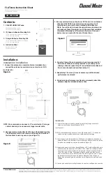
background image

3

Attach one end of a 75-ohm coax-
ial cable to the amplifier’s F-con-
nector labeled 

TO POWER SUPPLY

Note: Do not splice the cable or
install any in-line devices such as
splitters or filters. You can install a
grounding block (Cat. No. 15-909),
which dissipates DC current and
provides a connection point for a
static discharge ground rod. 

4. Use either standoffs or weather-

resistant electrical tape to secure
the cable to the antenna mast.
Use standoffs to secure the cable
to the building as you route the
cable to your TV. 

Notes: 

• If you use a power rotator for

your antenna, leave enough
cable slack for unrestrained
rotation of the upper section. 

• Leave a slight amount of slack

(called a drip loop) where the
cable enters your house. 

• Be sure to weatherproof all con-

nections, using plastic electrical
tape or a coaxial sealant. 

Installing the Power Supply 

Notes: 

• The power supply is designed for

indoor use only. 

• Do not mount the unit to any elec-

trical equipment or your TV set.
Choose a location for the power
supply near the TV or FM receiver,
and close to a standard AC outlet.

1. Drill a hole at the desired location

and thread the supplied screw into
the hole until its head extends
about 

1

/

8

 inch from the wall.

2. Align the power supply’s keyhole

slot with the screw head and slide
the power supply down.

3. Connect the coaxial cable from the

amplifier to the power supply’s

FROM AMPLIFIER

 terminal. Do not

overtighten the connector.

4. Connect one end of a short length

of cable to the power supply’s 

TO

TV

 terminal. 

15-1109.fm  Page 3  Thursday, July 15, 1999  10:41 AM

Summary of Contents for TV • FM High Gain Mast-Mount Antenna UHF/VHF/FM Amplifier with Switchable FM Trap

Page 1: ...if power fails or the connecting cable shorts Special Automatic Protection Cir cuit guards against cable shorts and prevents damage to connected re ceivers Surface Mounted Components assure long term...

Page 2: ...e to the amplifier s F connector labeled TO ANTENNA Attach the other end of this cable to the antenna s terminals using the supplied 300 to 75 ohm matching transformer if necessary Notes Be sure to fu...

Page 3: ...d a drip loop where the cable enters your house Be sure to weatherproof all con nections using plastic electrical tape or a coaxial sealant Installing the Power Supply Notes The power supply is design...

Page 4: ...FM splitter Cat No 15 1252 Caution Do not reverse the TO TV and FROM AMPLIFIER connec tions Voltage is present at the FROM AMPLIFIER terminal which might damage an improperly con nected receiver 6 Whe...

Page 5: ...than one TV Connect a Four Set Hybrid Splitter Cat No 15 1142 to TO TV and follow the splitter s owner s manual to make the connections to more than one audio video device Drip Loop Amplified Coupler...

Page 6: ...MIN for strong or nearby stations Automatic Protection Circuit The amplifier contains circuitry to guard against damage caused by a short anywhere in the cable from the amplifier to the receiving unit...

Page 7: ...a multiple re ceiver system Check all F connectors for dam age In particular examine the center pins Be sure the F connectors are properly attached Verify that the TV or FM receiver operates properly...

Page 8: ...he warranty period take the product and the RadioShack sales receipt as proof of purchase date to any RadioShack store RadioShack will at its option un less otherwise provided by law a correct the def...

Reviews: