background image

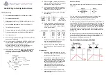
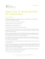
PICTORIAL DIAGRAM SEQUENTIAL   


TOP VIEW 


For sequential blinking follow steps 17b 
through 28b below. 

17b. (  )  Insert an NE2-1 neon lamps as shown in the 
pictorial  diagram.    Connect  one  lead  to  2.7  Meg 
resistor R1 and solder. 
 
18b. (  )  Insert an NE2-2 neon lamps as shown in the 
pictorial  diagram.    Connect  one  lead  to  2.7  Meg 
resistor R2 and solder. 
 
19b. (  )  Insert an NE2-3 neon lamps as shown in the 
pictorial  diagram.    Connect  one  lead  to  2.7  Meg 
resistor R3 and solder. 
 
20b. (  )  Insert an NE2-4 neon lamps as shown in the 
pictorial  diagram.    Connect  one  lead  to  2.7  Meg 
resistor R4 and solder. 
 
21b. (  )  Insert an NE2-5 neon lamps as shown in the 
pictorial  diagram.    Connect  one  lead  to  2.7  Meg 
resistor R5 and solder. 
 
22b. (  )  Insert .22 MFD capacitor C1 as shown in the 
pictorial diagram.  Connect one end to NE2-3 and the 
other end to NE2-5.  Solder each connection. 

23b. (  )  Insert .22 MFD capacitor C2 as shown in the 
pictorial diagram.  Connect one end to NE2-2 and the 
other end to NE2-5.  Solder each connection. 
 
24b. (  )  Insert .22 MFD capacitor C3 as shown in the 
pictorial diagram.  Connect one end to NE2-2 and the 
other end to NE2-4.  Solder each connection. 
 
25b. (  )  Insert .22 MFD capacitor C4 as shown in the 
pictorial diagram.  Connect one end to NE2-1 and the 
other end to NE2-4.  Solder each connection. 
 
26b. (  )  Insert .22 MFD capacitor C5 as shown in the 
pictorial diagram.  Connect one end to NE2-1 and the 
other end to NE2-3.  Solder each connection. 
 
27b. (  )  Remove 2-

1/2” insulation from one end of a 

7-

1/4”  piece  of  wire.    Remove  2

-

1/2”  i

nsulation  from 

the other end of the wire. 
 
28b. (  )  Insert the wire into the perfboard as shown 
in  the  pictorial  diagram.    Connect  one  end  to 
transformer T1 Pin 1 and solder.  Connect the other 
end to NE2-1 through NE2-5, and C1 through C5, and 
solder all leads. 
 

+

2            5            6
1            3            4

R1

R2

R3

R4

R5

T1

D1

R6

C6

C7

R7

-

6V

Q1

C1

C2

C4

C3

C5

NE2-

1

NE2-

2

NE2-

3

NE2-

4

NE2-

5

Summary of Contents for Science Fair Goofy-Lite 28-130

Page 1: ...n circuit This oscillator circuit converts the direct current coming from the battery to an alternating current The transformer then steps up the alternating 6 volt current to almost 200 volts at the transformer s secondary stage This voltage is high however the current very low and is not dangerous in any way The voltage then passes through the resistors R1 R5 and is stored in the capacitors C1 C...

Page 2: ...FS1 4CT52R475J 0 15 ea 1 10K Resistor R6 660 CFS1 4CT52R103J 0 15 1 15 Ohm Resistor R7 660 CFS1 4CT52R150J 0 17 5 NE2 Neon Lamp 606 A1A 0 28 ea 1 Battery Holder 12BH348 GR 1 28 2 Battery terminal block 534 8730 0 31 ea 1 Project case 546 1591GS BK 5 13 1 Perf Board 589 7100 45 4 99 1 22 Ga Solid Hookup Wire Black All part numbers and prices listed above are from Mouser as of March 2016 RECOMMENDED...

Page 3: ...rmer T1 Pin 4 and then solder the other end to transformer T1 Pin 5 5 Insert the negative and positive battery terminals into the perfboard positions indicated in the pictorial diagram If the battery terminals are loose in the perfboard apply a small blob of solder to keep them from falling out E B C 6 Mount transistor Q1 as shown in the pictorial diagram and compare with the diagram above Note th...

Page 4: ... Insert an NE2 3 neon lamps as shown in the pictorial diagram Connect one lead to 2 7 Meg resistor R3 20a Insert an NE2 4 neon lamps as shown in the pictorial diagram Connect one lead to 2 7 Meg resistor R4 21a Insert an NE2 5 neon lamps as shown in the pictorial diagram Connect one lead to 2 7 Meg resistor R5 22a Insert 22 MFD capacitor C1 as shown in the pictorial diagram Connect one lead to the...

Page 5: ... each connection 23b Insert 22 MFD capacitor C2 as shown in the pictorial diagram Connect one end to NE2 2 and the other end to NE2 5 Solder each connection 24b Insert 22 MFD capacitor C3 as shown in the pictorial diagram Connect one end to NE2 2 and the other end to NE2 4 Solder each connection 25b Insert 22 MFD capacitor C4 as shown in the pictorial diagram Connect one end to NE2 1 and the other...

Page 6: ...blink The sequential lights will change direction if you disconnect and connect the battery The lights have other interesting effects They seem to blink faster in the absence of light They seem to blink faster of they are touched on the side with your finger It is possible to extend the leads of the neon lamps so that they can be mounted through any type of cover you might wish to construct This u...

Reviews: