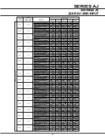
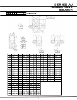

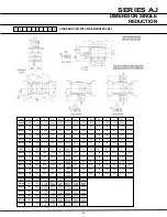

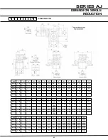


SERIES AJ
74
INSTALLATION
& MAINTENANCE
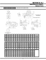
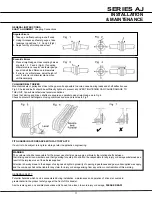
fEET ASSEMBLY (TYPES G, H, I)
1 Clean shaft extension with petroleum spirit
2 Remove paint from locating faces on gearcase with scraper and petroleum spirit
3 Secure feet (item 1, 2 or 3) to gear case with nuts and bolts provided to thumb tightness, in required operating position
4 Ensure foot pads are correctly seated
5 Secure to foundations with bolts to thumb tightness and line up unit
6 Tighten feet bolts to unit
7 Check shaft alignment (see page 77) and tighten down bolts. Series A units are provided with intergral feet for
mounting in the overdriven and underdriven positions. Feet type I are available to provide exact interchangeability with
previous well established Radicon adaptable Series 9 range.
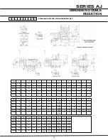
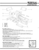
OUTPUT SHAfT ASSEMBLY
1 Clean outputshaft (item 4) and bore in gear unit with petroleum spirit
2 Fit keys into output shaft, ensuring they are firmly seated
3 Press shaft into gear unit bore to give desired shaft handling (Left or Right), until firmly up against shaft shoulder
4 Fit circlip (item 5) into groove in shaft on opposite side to extension
5 Tap blanking plug (item 6) into recess in gear case/end cover
NOTE: For reversing drives where end float is critical, it may be necessary to fit shims
behind the circlip fixing. These are available on request from application engineering.
fLANGE MOUNT UNIT (VERSION f)
1 Series A units are also available with circular output flanges located to the output
shaft cover with extended bolts. These are normally factory fitted
2 The output flange is provided with a female spigot recess facilitating accurate
location and concentricity with clients driven shaft
3 Flange to foundation fixing is by means of stud and nut, alternatively bolt and nut,
entered from the side of the driven machinery
4 Ensure facing of flange is thoroughly cleaned prior to mounting


