


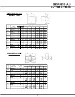


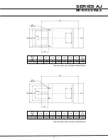
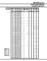
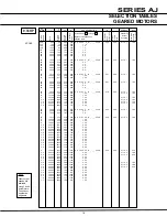

SERIES AJ
4
EXPLANATION & USE Of
RATINGS & SERVICE fACTORS
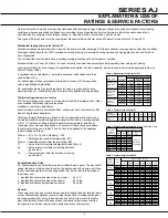
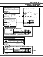
Gear unit selection is made by comparing actual loads with catalogue ratings. Catalogue ratings are based on a standard set of loading
conditions, whereas actual load conditions vary according to type of application. Service Factors are therefore used to calculate an
equivalent load to compare with catalogue ratings. i.e. Equivalent Load = Actual Load x Service Factor
Two types of Service Factor must be considered:- Mechanical Service Factor Fm and Thermal Service Factors Ft, Fp and FD
Mechanical ratings and service factor fM
Mechanical ratings measure capacity in terms of life and/or strength, assuming 10 hr/day continuous running under uniform load conditions.
Catalogue ratings allow for an 100% overload at starting, braking or momentarily during operation on aggregate once per hour for each
hour of operation.
The unit selected must therefore have a catalogue rating at least equal to half maximum overload.
Mechanical Service Factor Fm (Table 1) is used to modify the actual load according to daily operating time, and type of loading.
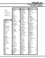
Load characteristics for a wide range of applications are detailed in Table 5 opposite, which are used in deciding the appropriate Service
Factor Fm from Table 1.
If overloads can be calculated, or accurately assessed, actual loads should be
used instead of Fm.
For units subject to frequent stop/start overloads in excess of 10 times per day,
refer to
application engineering
.
For applications where high inertia loads are involved e.g. crane travel drives,
slewing motion etc., unit selection should be referred to
application engineering
.
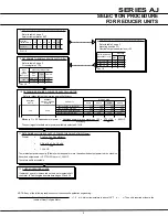
Thermal ratings and service factors
The Thermal ratings are a measure of the gear units ability to dissipate heat. If they
are exceeded the lubricant may overheat and
breakdown, resulting in gear failure.
Thermal factors are for units with fans fitted, un-fanned units to be referred to DB
Radicon Applications department.
Catalogue thermal limitations are based on the unit operating continuously in an
environment with an ambient temperature equal to 68oF and in mounting position
A, B or C. The thermal rating is affected by ambient temperature, duration of
running per hour and mounting position. To account for these varying conditions,
the service factors given in tables 2,3 and 4 should be applied to the catalogue
thermal ratings as follows:-
Ptherm = (Pt x Ft x Fp x Fd x efficiency) / 100
Pt
= Catalogue input power thermal rating (HP)
Ptherm = Allowable output power thermal rating (HP)
Ft
= Service factor for ambient temperature (see Table 2)
Fp
= Service factor for different mounting positions
(see Table 3)
Fd
= Thermal service factor for duration of running
(see Table 4)
Double Reduction Units
For double reduction units the factors given in tables 2 and 4 apply. The input shaft
speed referred to in table 4 should now be the input speed of the primary unit. New
factors should be applied for mounting position (Fp), which refer to the position of
the primary unit.
i Inputshaft horizontal and wheel- line horizontal
Fp = 1.0
ii Inputshaft horizontal and wheel-line vertical
Fp = 0.88
iii Inputshaft vertical and wheel-line horizontal
Fp = 0.68
General
When selecting units, use actual load required to be transmitted, not rating of prime
mover. Wherever possible use required output torque (lb-in). Catalogue also gives
input power rating (HP), being the power required from prime mover allowing for
gear unit efficiency. When units transmit less than rated output torque, required
input power may be reduced pro-rata to decide capacity of prime mover.
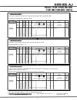
250
500
875
1160
1450
1750
2400
3500
280-610
730
860
280-610
730
860
280-610
730
860
280-610
730
860
280-610
730
860
280-610
730
860
280-610
730
860
280-610
730
860
1.0
1.0
1.0
1.0
1.0
1.0
1.0
1.0
1.0
1.0
1.0
1.0
1.0
1.0
1.0
1.0
1.0
1.0
1.0
1.0
1.0
1.0
1.0
1.0
1.46
1.44
1.46
1.46
1.38
1.46
1.46
1.34
1.41
1.46
1.30
1.37
1.46
1.28
1.34
1.46
1.26
1.32
1.46
1.22
1.30
1.46
1.13
1.24
1.72
1.52
1.72
1.72
1.56
1.72
1.72
1.47
1.60
1.72
1.43
1.54
1.72
1.39
1.50
1.72
1.36
1.46
1.72
1.30
1.42
1.72
1.23
1.34
1.96
1.92
1.96
1.96
1.75
1.96
1.96
1.64
1.79
1.96
1.56
1.72
1.96
1.52
1.66
1.96
1.47
1.61
1.96
1.39
1.55
1.96
1.30
1.45
2.32
2.26
2.32
2.32
2.02
2.32
2.32
1.84
2.07
2.32
1.75
1.96
2.32
1.69
1.88
2.32
1.63
1.81
2.32
1.53
1.75
2.32
1.41
1.61
2.86
2.75
2.86
2.86
2.38
2.86
2.86
2.16
2.45
2.86
2.05
2.32
2.86
1.97
2.21
2.86
1.89
2.14
2.86
1.75
2.03
2.86
1.58
1.85
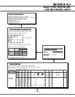
Input
shaft
speed
(Rev/min)
Unit
Size
>60
>50-60 >40-50 >30-40 >20-30
>20
% Running time per hour
Table 4. Thermal service factor fd
0
to 100
>100 to 200
>200 to 300
>300 to 400
>400 to 500
>500 to 600
>600 to 700
>700
Output
Speed
(Rev / min)
1.0
1.0
1.0
1.0
1.0
1.0
1.0
1.0
ABC
1.0
1.0
1.0
1.0
1.0
1.0
1.0
1.0
DEF
1.0
1.0
1.0
1.0
1.0
1.0
1.0
1.0
GHJ
KMN
Refer to
Application
Engineering
PST
WXy
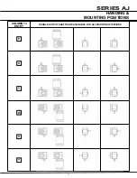
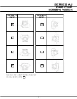
Mounting Position (See pages 9 and 10)
Table 3. Thermal service factor fp
(Single Reduction units)
Ambient
temperature
o
F
Factor Ft
-20
0
20
40
60
68
80
100 120
1.64 1.50 1.36 1.22 1.07 1.00 0.92 0.77 0.63
Table 2. Thermal service factor ft
Prime mover
Electric motor,
steam turbine
or
hydraulic motor
Multi-cylinder
internal
combustion
engine
Single cylinder
internal
combustion
engine
Duration of
service hrs
per day
Under 3
3 to 10
Over 10
Under 3
3 to 10
Over 10
Under 3
3 to 10
Over 10
Load classification-driven machine
Table 1. Mechanical service factor fm
0.80
1.00
1.25
1.00
1.25
1.50
1.25
1.50
1.75
Uniform
0.80
1.00
1.25
1.00
1.25
1.50
1.25
1.50
1.75
Moderate
Shock
0.80
1.00
1.25
1.00
1.25
1.50
1.25
1.50
1.75
Heavy
Shock


