Additional Information on the Interface Signals
PIN
Name Definition _____
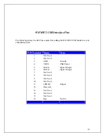
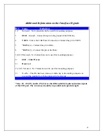
1,2 Not used – No Connection can be used for mounting purposes
3
GND
– Ground – Connect this pin to the ground of the USB bus
4
VBUS
– This is the USB Power Connection. Connect this pin to VBUS
5 *
DATA (-) -
Connect this pin to Data –
6
*
DATA (+) -
nnect th
Data +
Co
is pin to the
7,8,9,10 Not used – No Connection can be used for mounting purposes
11
LED - Link
Process
12
Reserved
13,14,15 Not used – N
onnecti
sed for m
o C
on can be u
ounting purposes
16
No Pin – Thi
has be
. Add a k y to the mating connector to
s Pin
en removed
e
prevent the m
le from
odu
being plugged in backwards.
*
11
Note: D+ (Pin 15) and D- (Pin 16) are the differential data plus and minus signals
of the USB port. The two traces should be in parallel and equal in length.


