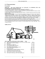
background image

INSTALLATION INSTRUCTIONS 


21

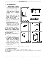
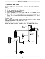
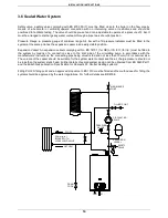
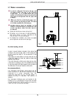
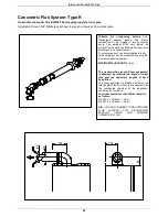
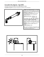
Concentric Flue System- Type K 

Horizontal concentric flue kit Ø60/100 mm polypropylene inner pipe. 

Adjustable through 360°.Discharges exhaust fumes an d draws air from atmosphere. 


Suitable 

for 

condensing 

boilers 

only. 

Discharges 

exhaust 

gases 

and 

draws 

combustion  air  by  means  of  two  concentric 
ducts.  The  external  Ø100  duct  draws  the 
combustion air while the Ø60 plastic inner duct 
discharges the exhaust fumes.


The discharge duct can be terminated directly 
to the outside or can be connected to a suitable 
plume management system.  
 
MAXIMUM FLUE LENGTH  : 6 m 
 
 
The maximum flue length (linear equivalent) 
is  obtained  by  totalling  the  length  of  linear 
pipe  and  the  equivalent  lengths  of  each 
bend fitted. 


The  linear  equivalent  is  intended  as  being  the 
total length of the duct from the connection with 
the  combustion  chamber  of  the  appliance, 
excluding the first bend. 
The linear equivalent of additional bends is 
as follows: 
Ø 60/100  x 90° bend  = 0.8 m.    
Ø 60/100  x 45° bend  = 0.5 m.    


N.B.USE ONLY RADIANT TYPE-APPROVED 
FLUE 

SYSTEMS 

FOR 

DISCHARGING 

EXHAUST 

GASES 

AND 

DRAWING 

COMBUSTION  AIR.  


8

0

130

160

6

0

1

0

0

Summary of Contents for RK 18

Page 1: ...ance instructions CE 0694 RK 18_25 OV RAD ING MAN INST 1104A DIGITECH 2 REGNO UNITO EXTRAHEAT CBD Technical specification RADIANT BRUCIATORI S p A Montelabbate PU ITALY ENGLISH Instruction Manual for...

Page 2: ......

Page 3: ...ter connection 15 3 8 Condensate drain 16 3 9 Gas connection 17 3 10Electrical connections 18 3 11Flue connections 20 4 Commissioning the appliance authorised personnel 4 1 General warnings 26 4 2 Fil...

Page 4: ...lation operation and maintenance manual forms an integral and essential part of the product and must be kept near the appliance always The warnings contained in this chapter have been written for the...

Page 5: ...gas leaks Prior to start up the central heating pipes should be flushed to remove any residues that could compromise the operation of the appliance The appliance can be regarded as being electrically...

Page 6: ...highly functional unit that is easy to install and simple to operate In its simplicity the wall mounted appliance is equipped with all the appropriate accessories required to make it a fully independ...

Page 7: ...ure heating bar 3 Min working pressure heating bar 0 3 Dimensions Boiler casing size Width mm 410 Height mm 730 Depth mm 290 Weight net kg 31 33 Hydraulic connections Central Heating Flow connection m...

Page 8: ...Pr 2 51 2 43 2 20 2 10 Flue gas temperature 50 30 C Pn C 50 8 53 Flue gas temperature 80 60 C Pn C 71 65 Flue Mass 50 30 C Pn Pr Kg h 29 95 6 65 42 50 15 30 Flue Mass 80 60 C Pn Pr Kg h 28 32 6 49 39...

Page 9: ...INSTALLATION INSTRUCTIONS 6 HF HR 410 730 290 G 107 199 41 164 149 50 51 131 2 2 Dimensions LEGEND HR HEATING RETURN mm 22 HF HEATING FLOW mm 22 G GAS mm 15...

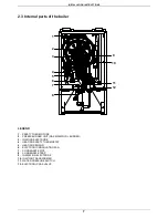
Page 10: ...END 1 SAFETY THERMO FUSE 2 PREMIX BURNER UNIT GAS MANIFOLD BURNER 3 IGNITION ELECTRODE 4 HEATING SAFETY THERMOSTAT 5 HEATING SENSOR 6 ELECTRONIC MODULATING FAN 7 CONDENSATE PIPE 8 CONDENSATE TRAP 9 IO...

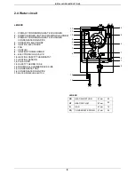
Page 11: ...XCHANGER CONDENSATE DRAIN PIPE 4 IONISATION ELECTRODE 5 IGNITION ELECTRODE 6 FAN 7 VENTURI 8 IGNITION TRANSFORMER 9 ELECTRONIC GAS VALVE 10 HEATING SAFETY THERMOSTAT 11 HEATING SENSOR 12 FLUE HOOD 13...

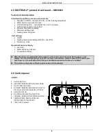
Page 12: ...eficiency indicator Temperature display When the boiler is switched off at the switch on the control panel the word OFF appears on the display The central heating frost protection system nevertheless...

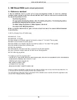
Page 13: ...and 3 rd family gases BS 5449 Forced circulation hot water systems BS 6700 Installation of cold water supplies for domestic purposes 1st 2nd and 3 rd family gases BS 6798 Installation of gas fired ho...

Page 14: ...are fully recyclable It is recommended that the packing material is only removed prior to installing the boiler The manufacturer will not be held responsible for damage caused by incorrect storage of...

Page 15: ...sary clearances indicated in figure 1 are respected To make the installation easier the boiler is supplied with a template to enable the pipe connections to be positioned prior to fixing the appliance...

Page 16: ...and flushing agents descalers should be suitable for all system metals They should be British Standars and Water Council approved Non acidity or alkalinity is desirable h For installations that inclu...

Page 17: ...for GB or I S 813 for I E must be fitted to the system by means of a connection close to the inlet side of the circulating pump in accordance with the manufacturers instructions the connecting pipe be...

Page 18: ...its in the primary heat exchanger the mains supply water to the heating circuit must be treated according to the requirements of local standards This treatment is indispensable in the case where the c...

Page 19: ...insulated to protect against frost It is also recommended that the pipe diameter is increased to 32mm 8 If the boiler is fitted in an unheated location the entire condensate discharge pipe should be...

Page 20: ...must be a minimum of a 22 mm diameter pipe with an uninterrupted supply from meter to boiler and comply with current standards and regulations Check the internal and external seals of the gas supply s...

Page 21: ...connection to the mains electricity supply must be via a single pole switch with at least 3 millimetres gap between open contacts mounted upstream of the appliance Make sure that the positions of the...

Page 22: ...B as follows Connect the earth wire normally coloured green yellow to the terminal marked with the earth symbol Connect the neutral wire normally coloured blue to the terminal marked with the letter N...

Page 23: ...minal is fitted less than 2m 6 6ft above a balcony above ground or above a flat roof to which people have access the terminal MUST be protected by a purpose designed guard Where the terminal is fitted...

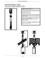
Page 24: ...can be terminated directly to the outside or can be connected to a suitable plume management system MAXIMUM FLUE LENGTH 6 m The maximum flue length linear equivalent is obtained by totalling the lengt...

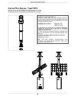
Page 25: ...minated directly to the outside or can be connected to a suitable plume management system MAXIMUM FLUE LENGTH RK 18 OV 12 m RK 25 OV 10 m The maximum flue length linear equivalent is obtained by total...

Page 26: ...inear equivalent is obtained by summing the length of linear pipe and the equivalent lengths of each bend fitted The linear equivalent is intended as being the total length of the duct exhaust dischar...

Page 27: ...r duct discharges the exhaust fumes MAXIMUM FLUE LENGTH 6 m The maximum flue length linear equivalent is obtained by totalling the length of linear pipe and the equivalent lengths of each bend fitted...

Page 28: ...ir while the 80 plastic inner duct discharges the exhaust fumes MAXIMUM FLUE LENGTH RK 18 OV 12 m RK 25 OV 10 m The maximum flue length linear equivalent is obtained by totalling the length of linear...

Page 29: ...te 230 V 50 Hz and that the live neutral and earth wires are connected properly Also make sure that the earth connection is sound Check the seals on the gas supply pipe from the mains and make sure th...

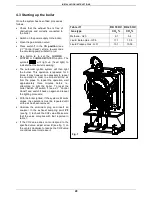
Page 30: ...filling operation is carried out as follows see fig 1 Remove plug T and fill the trap S three quarters full with water Replace plug T and connect the drainpipe P into a condensate discharge trap confo...

Page 31: ...er to eliminate all the air from the pipes To repeat the operation wait approximately three minutes before re attempting to light the boiler To reset the boiler Switch off switch 1 see 2 7 Control Pan...

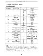
Page 32: ...01 default 02 03 04 00 0sec 01 50 sec 02 100 sec 03 200 sec 04 400 sec P05 Water hammer prevention function not applicable 00 01 00 Off 01 On P06 D H W priority function not applicable 00 01 00 Off 0...

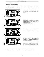
Page 33: ...eping buttons and pressed Wait for P 00 to appear on the display 3 Release buttons and 4 Keep button S pressed and use button to select the parameter to modify 5 Release button S then re press and rel...

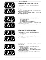
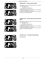
Page 34: ...will appear on the display 8 Switch off the appliance and switch it back on again to render the new parameter operative PARAMETER P02 SELECTS THE TYPE OF GAS 6 Use buttons and to modify the value of t...

Page 35: ...0 seconds 03 200 seconds 04 400 seconds 7 Press and release button S to confirm The parameter number P04 will appear on the display 8 Switch off the appliance and switch it back on again to render the...

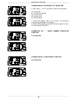
Page 36: ...e and switch it back on again to render the new parameter operative PARAMETER P08 CENTRAL HEATING PUMP OVERRUN TIMER 6 Use buttons and to modify the value of the parameter within the prescribed limits...

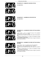
Page 37: ...e parameter number P12 will appear on the display 8 Switch off the appliance and switch it back on again to render the new parameter operative PARAMETER P13 MAXIMUM FAN SPEED SETTING CENTRAL HEATING 6...

Page 38: ...back on again to render the new parameter operative PARAMETER P16 TELEPHONE CONTROL ACTIVATION 6 If a telephone interface is installed enable the board by setting parameter P16 at 01 7 Press and rele...

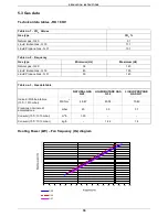
Page 39: ...Gas G 31 10 1 Table no 2 Frequency Gas type Minimum Hz Maximum Hz Natural gas G20 38 145 Liquid Butan Gas G 30 43 135 Liquid Propane Gas G 31 50 143 Table no 3 Gas data table NATURAL GAS G20 LIQUID B...

Page 40: ...iquid Propane Gas G 31 60 149 Table no 3 Gas data table NATURAL GAS G20 LIQUID BUTANE GAS G30 LIQUID PROPANE GAS G31 Indice di Wobbe inferiore 15 C 1013 mbar MJ Nm3 45 67 80 58 70 69 Pressione nominal...

Page 41: ...Conversion is performed as follows Select the new gas type by changing parameter no P02 see Parameters table 5 2 Unscrew the aluminium plug and insert the analyser in the exhaust sampling point PF see...

Page 42: ...if necessary proceed in line with section Commissioning the boiler Remove and clean any oxidation from the burner Check that the seal of the room sealed chamber is undamaged and positioned correctly...

Page 43: ...the left and right control panel support brackets see fig 5 and pull them outwards at the same time rotating the panel downwards Unscrew the four fixing screws see fig 6 and remove the panel back piec...

Page 44: ...responsible for damage to any of the boiler s components caused by non compliance with this instruction For all maintenance operations requiring removal of the boiler casing refer to the procedures d...

Page 45: ...altering their positions with respect to the burner Clean the burner cylinder using a non metal brush and without damaging the ceramic fibre Check the integrity of the washer on the cover of the burn...

Page 46: ...stances between the electrodes and the burner are respected to avoid a boiler malfunction Safety thermostat see fig 2 Disconnect the connecting wire Unscrew the fixing screws and remove the thermostat...

Page 47: ...plies and carry out gas soundness test Electric fan see fig 2 Remove and dismantle the entire burner unit see 6 6 1 Cleaning the burner unit Use an 8 mm spanner to unscrew the four nuts securing the e...

Page 48: ...turn pipes Remove the support brackets and pull out the heat exchanger Remove the regulation sensor from the old heat exchanger and refit it together with the two condensate drainpipes to the new one...

Page 49: ...d re assemble the components following the above procedure in reverse order Switch on the electricity water and gas supplies and regulate the boiler see 5 3 Gas data The preset parameters of the print...

Page 50: ...rown light blue brown light blue orange red light blue light blue Relay black black VG PRINTED CIRCUIT BOARD DIGITECH 2 SM30003 COD 40 00016 N L M11 light blue brown M11 Legend IG Main Switch TS Safet...

Page 51: ...j THERMOSTAT CABLE DISCONNECTED i REPLACE PART j CHECK THE WIRING E03 FLUE SAFETY THERMOFUSE k THERMOFUSE BROKEN l THERMOSTAT CABLE DISCONNECTED m THERMOFUSE LOCK OUT HIGH FLUE TEMPERATURE k REPLACE...

Page 52: ...tion Pressing the boiler off button deactivates the function The Flue test function operates the boiler at the maximum heating pressure for 15 minutes without any modulation The function is useful for...

Page 53: ...ONDENSING EXCHANGER 4 1 CBD COMPLETE 35031LA IGNITION ELECTRODE 35032LA IONISATION ELECTRODE 36067LA ELECTRONIC GAS VALVE 36068LA VENTURI 37032LA FAN PX128 203 40 00016 PRINTED CIRCUIT BOARD DIGITECH...

Page 54: ......

Page 55: ......

Page 56: ...N PURPOSES ONLY AND ARE NOT BINDING THE COMPANY RESERVES THE RIGHT TO APPLY VARIATIONS WITHOUT PRIOR NOTIFICATION NEITHER WILL THE COMPANY BE HELD RESPONSIBLE FOR ANY INACCURACIES IN THIS HANDBOOK DER...

Reviews: