


14 of 16
TC-1000 Radar Speed Sign Installation Manual MN0018 v21.01
Making the Power Connections (cont’d)
A/C Power Connections for the TC-1000A
T
he signs will accept direct connection to a power supply between 100v and 240v. Higher voltage supplies will
require a customer supplied step-down transformer. Branch circuits should have a 5 amp circuit breaker installed for
protection and power cycle convenience
1) Locate the open outlet box at bottom of radar speed sign
2) Feed incoming AC power wires through conduit connection
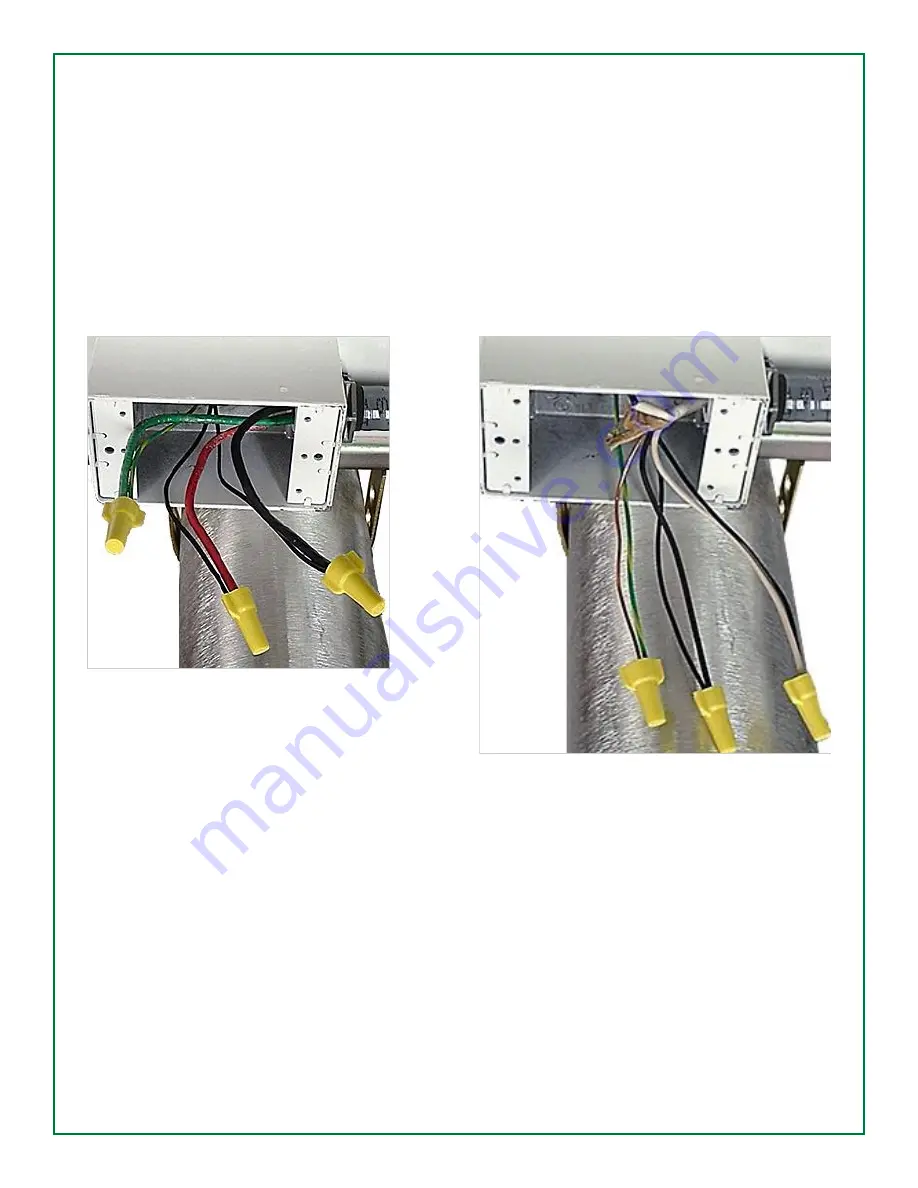
3) Connect the exposed black, black, and green wires as shown below in Photo 1A or 1B
4) Either of the two black wires can connect to the LINE or NEUTRAL incoming wires
When wiring is complete and has been inspected, cycle the AC power on and observe the sign display. The sign will
flash its serial number and code version, and resume normal operation as indicated by blinking of the blue LED in the
center of the display.
Photo 1A – Red, Black, Green
Photo 1B – Black, White, Copper


