12
RabbitCore RCM2200
2.3.4 Connect Power
When all other connections have been made, you can connect power to the RCM2200 Pro-
totyping Board.
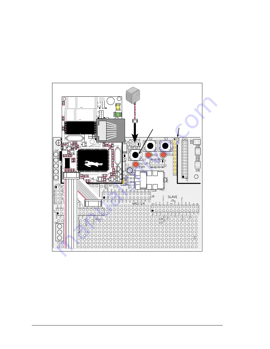
Hook the connector from the wall transformer to header J5 on the Prototyping Board as
shown in Figure 6 below. The connector may be attached either way as long as it is not
offset to one side.
Figure 6. Power Supply Connections
Plug in the wall transformer. The power LED on the Prototyping Board should light up.
The RCM2200 and the Prototyping Board are now ready to be used.
NOTE: A
RESET
button is provided on the Prototyping Board to allow hardware reset
without disconnecting power.
To power down the Prototyping Board, unplug the power connector from J5. You should
disconnect power before making any circuit adjustments in the prototyping area, changing
any connections to the board, or removing the RabbitCore module from the board.
Reset
Switch
AC Adapter
J1
R2
C3
D2 R7
C27
R8
R36
RT
1
R41
R37
R38
D1
R39
Y2
C2
C1
U8
U7
U3
U6
C7
GND
GND
EGND
DS2
LNK
ACT
DS1
R19
Q3
Q4
Q5
Q2
R1
Y1
C4 C17
C8
R9
R13
R11
U1
BT1
R
1
5
C12
R17
R20
C13
Y3
R16
R22
R21
C14
R
18
C25
C28
D3
J2
JP4
JP3
JP1
JP6
C30
JP2
JP5
C29
U2
RCM2200
DIAG
PROG
Prototyping
Board
Summary of Contents for RCM2000 Series
Page 18: ...14 RabbitCore RCM2200...
Page 26: ...22 RabbitCore RCM2200...
Page 38: ...34 RabbitCore RCM2200...
Page 40: ...36 RabbitCore RCM2200...
Page 43: ...C NONE...
Page 46: ......


