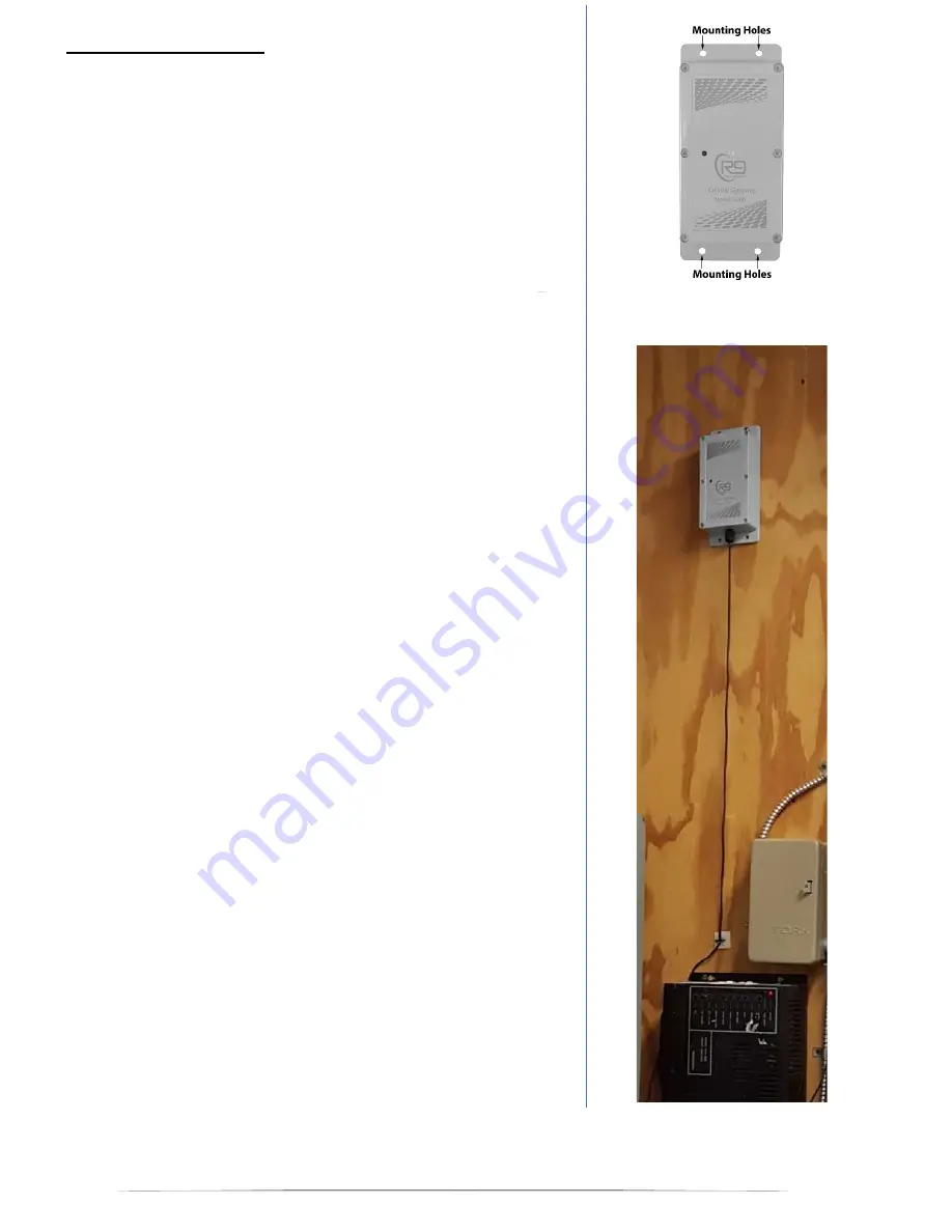
3
Figure 2
Installation Instructions:
After a suitable installation location has been identified for the gateway,
follow the installation steps below:
Step 1
Setup Gateway and Sensor Nodes in Portal
- use the Safezone
portal dashboard to setup your account, gateway, and sensor node
devices. Steps for online setup of the node/gateway system are
located in the
R9 Online Portal User Guide
. Log in and select the
configuration menu to input your device information.
Step 2
Test Gateway Operation
- Before permanently installing the gateway
device, ensure the gateway and node devices have a good wireless
connection,
after placing the devices in the general area of install
(If
system communication / reception is not possible, the units will have to
be moved for improved wireless performance. Except in extreme
cases, your system will have plenty of wireless range for optimal
performance.
Test Gateway
- Cellular LTE service for the gateway is good as
indicated by two “quick blink” green LED flashes at the start of the LED
indication sequence (first two of four blinks). If first two LED blinks are
green, LTE service is good. The gateway does not have to be
provisioned in the portal for LTE service indication. The gateway only
has to be powered on by plugging in to wall power.
Test Sensor Node(s)
- Gateway and sensor node devices must be
provisioned in the online portal for node connectivity to be tested.
Wireless connection from the gateway to each node device is good if
the node devices will pair to the gateway. Quick press the pair button
on the node (marked P). If the LED flashes green, the node is paired to
the gateway and the wireless connection is good. If the LED flashes
red, the node device has not paired yet. After the entry of the device
serial numbers into the portal, the pairing should happen within 3 to10
minutes.
There is no power switch on the gateway device. When the G200
gateway is plugged into AC power for the first time, the unit will power
on and initialize (boot up). After ~ 30 seconds of initialization, the
gateway will output a faint audible chime, and the front LED will start to
flash. The unit will then remain powered by the internal battery, even if
the AC plug is disconnected from the wall socket. Note that pressing
the reset button while the gateway is un-plugged will cause the unit to
power down.
AC power outlets located inside closets, or in the back of industrial
buildings may not be active. If gateway power is lost, or the gateway is
moved to an up-powered plug, then the second “long green flash” in the
LED flash sequence will turn into two red “quick LED flashes”. See the
Gateway Hardware User Guide
for more information on the LED
status indication. Two LED red flashes indicates that AC power outlet
is off or not powered (third and fourth blinks).
Step 3
Mount the Gateway
– Mount the gateway (up high) using the two
provided screws. Mount using one screw at top, and one at bottom.
Screws should be at a diagonal to each other. Place small holes in the
wall to allow the screws to start. Ensure the gateway is oriented so that
the cables are exiting from the bottom of the unit.
Note that it is ok to
place the gateway on a shelf, desk, or other location without
permanent mounting
. Alternatively, some customers use double
sided foam tape to mount the gateway, as it is very light.
Step 4
Power Gateway Device
- Plug the gateway power supply into an AC
wall outlet (120V, 60 Hz. for USA). Bundle any excess power cable
and make sure it is out of the way.


