TEX1003TFT
5
/ 34
User Manual
Rev. 1.1 - 27/05/21
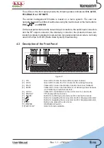
Five LEDs on the front panel provide the following status indications:
ON
,
LOCK
,
FOLDBACK
and
RF MUTE
.
The exciter management firmware is based on a menu system. The user can
navigate between the different submenus using the touchscreen or the four buttons:
ESC
, , , and
ENTER
.
On the rear panel there are the network input connectors, the audio input connectors
and the RF output connector, the telemetry connector, the protection fuses, two
inputs for signals modulated on sub-carriers by special external encoders, normally
used in Europe for RDS (Radio Data System) broadcasting.
4.3 Description of the Front Panel
LOCAL
MUTE
LOCK
FOLD.
ON
ENTER
ELETTRONICA
Figure 4.1
[1] ON
Green LED, lit when the transmitter is power enabled.
[2] LOCK
Green LED, lit when the PLL is locked to the working frequency.
[3] FOLD.
Yellow LED, lit when the limitation function intervenes (foldback).
[4] MUTE
Yellow LED, lit when the transmitter is not delivering power because
it is inhibited by an external interlock.
[5] LOCAL
Yellow LED, illuminated when the exciter is set to Local mode.
[6] DISPLAY
TFT display with touchscreen.
[7] ENTER
Button for confirming a parameter and for entering the menus.
[8]
Button for navigating the menu system and for changing parameters.
[9]
Button for navigating the menu system and for changing parameters.
[10] ESC
Button to be pressed to exit a menu.
[11] POWER
ON/STAND-BY switch.
[12] AIR FLOW
Grids for forced ventilation.
Summary of Contents for TEX1003TFT
Page 1: ...TEX1003 TEX1003TFT TFT USER MANUAL VOLUME1 Manufactured by R V R ELETTRONICA Italia ...
Page 41: ...TEX1003TFT 35 34 User Manual Rev 1 1 27 05 21 9 4 Option CNT7 8 150 R F OUTPUT Type 7 8 50Ω ...
Page 42: ...36 34 User Manual Rev 1 1 27 05 21 TEX1003TFT This page was intentionally left blank ...


