background image

5

290/350 Operator and Parts Manual V13.1210

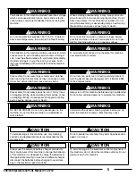
WARNING

The batteries in this machine produce hazardous voltage 
which can cause electrical shock, burns and/or electro-
cution. Always disconnect batteries before servicing this 
machine.

WARNING

When climbing or descending ramps, always drive ma-
chine forward. To avoid overturning the machine, Do not 
back down ramps. Do not drive across inclines. Do not 
turn while ascending or descending ramps. Overturning 
the machine can cause serious injury or death.

WARNING

Do not use water that exceeds 135

°

F / 57

°

C.  If water is 

above said temperature, this will void the Tank Warranty.

WARNING

Do not park this machine on ramps or slopes. Always 
park this machine on a level, hard surface. Do not oper-
ate this machine outdoors or on uneven surfaces.

WARNING

The batteries in this machine contain sulfuric acid, which 
causes burns to skin. If battery acid contacts clothing or 
skin, rinse the effected area with cold water immediately. 
If battery acid gets on your face or in your eyes, flush 
the area immediately with cold water and seek medical 
attention.

WARNING

To avoid electrical shock, do not operate this machine 
over electrical floor outlets.

WARNING

Dress safely. Do not wear rings or metal wrist watches 
when servicing this machine, as they can cause an elec-
trical short circuit which can cause serious burns.

WARNING

Do not remove, paint over or destroy warning decals. If 
warning decals become damaged, call 1-262-681-3583 
for free replacements.

WARNING

Dress safely. Do not wear a neck tie, scarf, or any loose 
or dangling clothing while operating this machine. Loose 
or dangling clothing or neck-wear can tangle in rotating 
parts, causing serious injury or death.

WARNING

Always turn off this machine before leaving it unattended. 
Do not allow untrained persons to operate this machine.

WARNING

NO EXTRA RIDERS. Do not carry passengers on this 
machine. Do not use this machine as a stepladder or 
work platform.

WARNING

Understand the dynamic braking system before you op-
erate the machine on ramps.  Machine may coast.

CAUTION

To avoid damage to this machine, use only cleaning 
solutions and replacement parts recommended by the 
manufacturer.

CAUTION

Do not operate this machine if any parts have been dam-
aged or removed.

CAUTION

Always use the automatic battery charger provided by 
the manufacturer of this machine to charge the batteries 
of this machine. It is designed to charge the batteries at 
the appropriate rate. If you must use a different charger, 
disconnect the batteries before charging to avoid dam-
age to the electronic speed controller.

CAUTION

To avoid damage to the electronic control components of 
this machine, Do not store this machine outdoors. Do not 
pressure wash this machine. 

Summary of Contents for 290 Series

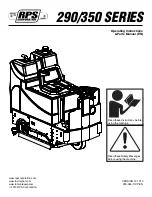
Page 1: ...ns Parts Manual EN www rpscorporation com www factorycat com VERSION 13 1210 www tomcatequip com 290 350 OP P EN 2013 RPS Corporation Read these Instructions before using the machine Read these Safety...

Page 2: ......

Page 3: ...3 ONE PASS SCRUBBING 13 OPERATING HINTS 14 DRAINING RECOVERY TANK 14 DRAINING SOLUTION TANK 14 BATTERY CHARGING 15 CHARGER SPECIFICATIONS 15 MAINTENANCE 16 DAILY MAINTENANCE 16 WEEKLY MAINTENANCE 16 M...

Page 4: ...an important responsibility DO NOT OPERATE THIS MACHINE UNLESS You are trained and authorized to do so You have read and understood this Operator s Manual On surfaces with greater than a 2 grade unle...

Page 5: ...ine as they can cause an elec trical short circuit which can cause serious burns WARNING Do not remove paint over or destroy warning decals If warning decals become damaged call 1 262 681 3583 for fre...

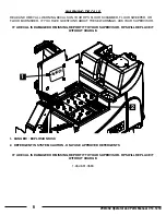
Page 6: ...HAVE QUESTIONS ABOUT THESE WARNINGS ASK YOUR SUPERVISOR IF A DECAL IS DAMAGED OR MISSING REPORT IT TO YOUR SUPERVISOR RPS WILL REPLACE IT WITHOUT CHARGE 1 DANGER EXPLOSION RISK 2 DETERGENT IN SYSTEM...

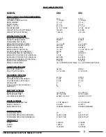
Page 7: ...MOTOR POWER CYLINDRICAL 800 RPM 800 RPM BRUSH MOTOR SPEED CYLINDRICAL 800 RPM 800 RPM BRUSH DOWN PRESSURE 0 200 LB 0 250 LB BRUSH ADJUSTMENT 5 AUTOMATIC SETTINGS 5 AUTOMATIC SETTINGS SOLUTION SYSTEM S...

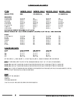
Page 8: ...422BR N A 18 422BR N A GREEN 15 422G N A 18 422G N A BLUE 15 422B N A 18 422B N A RED 15 422R N A 18 422R N A WHITE 15 422W N A 18 422W N A SQUEEGEE KITS SIZE GUM RUBBER NEOPRENE LINATEX 32 22 770G 2...

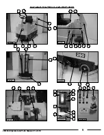
Page 9: ...9 290 350 Operator and Parts Manual V13 1210 FIGURE 2 FIGURE 3 FIGURE 4 FIGURE 5 FIGURE 6A FIGURE 1 FIGURE 6B MACHINE CONTROLS AND FEATURES...

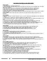
Page 10: ...KEEP FREE AND CLEAR OF BLOCKAGE 20 VACUUM HOSE MAIN VACUUM HOSE FROM VACUUM TO RECOVERY TANK 21 SQUEEGEE BLADE SQUEEGEES WATER TO BE RECOVERED BY THE VACUUM HOSE SEE FIGURE 4 22 SIDE DOOR PROVIDES EA...

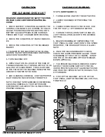
Page 11: ...OSITION AND RE MOVE KEY 2 HINGE OPEN THE BATTERY ACCESS LID TO ACCESS THE BATTERY COMPARTMENT 3 ALL OF THE FOUR BATTERY CABLES ARE CONNECT ED TO THE BATTERIES LOCATE ANY LOOSE ONES AND CONNECT TO THE...

Page 12: ...ON THE WIPERS FIRST TO CLOSE SIDE DOOR AND DEPRESS THE LATCH UNTIL THE DOOR IS SECURED SEE FIGURE 12 ATTACHING CYLINDRICAL BRUSHES 1 TURN ON MACHINE POWER 2 RAISE THE SCRUB DECK BY DEPRESSING THE BRUS...

Page 13: ...ILUTION RATIO INDICATED ON THE BOTTLE NOTE USE ONLY NONFLAMMABLE COMMERCIAL CLEANING CHEMICALS YOUR AUTHORIZED DISTRIBUTOR CAN ASSIST YOU IN SELECTING A PROPER CHEMICAL ONE PASS SCRUBBING STEPS SEE FI...

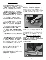
Page 14: ...AYS KEEP AN EYE ON YOUR GAUGES THEY LET YOU KNOW THE STATUS OF A PARTICULAR SYS TEM AT A GLANCE IF YOUR BATTERY GAUGE IS READING LOW YOU MUST STOP IMMEDIATELY AND RECHARGE RUNNING THE BATTERIES DEAD W...

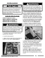
Page 15: ...sulfuric acid which causes burns to skin If battery acid contacts clothing or skin rinse the effected area with cold water immediately If battery acid gets on your face or in your eyes flush the area...

Page 16: ...RIES BATTERIES SHOULD BE FILLED APPROXIMATELY 3 4 TO 1 ABOVE THE PLATES OVERFILLING WILL CAUSE THE BATTERIES TO LEAK DURING CHARGING THE CHARGING PROCESS CREATES GAS BUBBLES INSIDE THE BATTERY WHICH E...

Page 17: ...CATES THE TOTAL NUMBER OF HOURS THAT THE MACHINE HAS BEEN ON 6 SCRUB BRUSH HOUR METER INDICATES THE TOTAL NUMBER OF HOURS THAT THE BRUSH MO TORS HAVE BEEN USED 7 TRANSPORT HOUR METER INDICATES THE TOT...

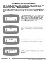
Page 18: ...THIS EQUIP MENT 1 7601 AND 7602 ERROR SCRUB DECK CURRENT OVER LOAD THIS CAN OCCUR WHEN DRIVING OVER A BUMP IN THE FLOOR TO RESTART TURN OFF THE KEY AND TURN IT ON AGAIN TO AVOID THIS ERROR EITHER SLOW...

Page 19: ...ies immediately All 081x codes Throttle wiring short or open circuits 0816 and 0817 can be caused by incorrect programming of the ISO test parameter Memory corrupt Replace Controller if not cleared by...

Page 20: ...vacuum motors or wiring Check the Vac motor connection on the Trio and check the wiring from this connector down to the Vac motor and checking connections all the way Otherwise possible Vac motor fau...

Page 21: ...ER OR WIRES CONTACT LOCAL SERVICING DEALER FAULTY DRIVE MOTOR CONTACT LOCAL SERVICING DEALER FAULTY WIRING CONTACT LOCAL SERVICING DEALER CARBON BRUSHES WORN CONTACT LOCAL SERVICING DEALER VACUUM MOTO...

Page 22: ...CONTACT LOCAL SERVICING DEALER TANK GASKET FAULTY CONTACT LOCAL SERVICING DEALER DRAIN PLUG LOOSE TIGHTEN LID VAC MOTOR FAULTY CONTACT LOCAL SERVICING DEALER BATTERY CHARGE LOW CHARGE BATTERIES OVERN...

Page 23: ...ECOVERY TANK FLUSH RECOVERY TANK CLEAN VACUUM SCREEN ROTATE REAR SQUEEGEE BLADE CHECK BATTERY WATER LEVEL CHECK BATTERY VOLTAGE CHECK CHARGER CONDITION CHECK BATTERY CONNECTIONS CHECK CHEMICAL LEVEL C...

Page 24: ...cleaning the dust filter emptying out the debris hopper and correct installation Correct operation of the main broom and side broom levers and understands to park with brushes in UP position Trained...

Page 25: ...EDGE ORBITZ isolators 250 hours on average Squeegee Blades Wiper Blades Skirts and Curtains Caster Wheels Squeegee Wheels and Bumpers Lights Strobe Headlights or Bulbs Chains and Belts Filters Screens...

Page 26: ...290 350 Operator and Parts Manual V13 1210 26...

Page 27: ...N SOME PARTS ARE MADE IN RED AND YELLOW IF YOU NEED YELLOW PARTS USE THE ALTERNATE PART NUMBER WHICH WILL START WITH 291 XXXX IF YOU NEED RED PARTS USE THE NORMAL PART NUMBER THAT WILL START WITH 290...

Page 28: ...ts Manual V13 1210 28 To Scrubhead 12 26 47 20 14 51 25 2 9 4 38 3 7 16 17 18 19 13 22 23 24 6 5 27 28 30 31 34 33 35 36 37 11 39 41 42 43 44 45 46 29 1 43 42 10 33 21 15 36 35 26 40 34 40 8 48 49 50...

Page 29: ...G CLEAR TUBE 1 22 H 99001 FW 3 8 SS 6 23 H 71065 LW 5 16 SS 6 24 H 70053 HCS 5 16 18 X 3 4 SS 6 25 290 4159 1 2 ID X 3 4 OD X 15 0 LG CLEAR TUBE 1 26 H NJ04C JNYL 1 4 20 SS 2 27 5 447 1 2 NPT TO 1 2 B...

Page 30: ...ual V13 1210 30 10 14 3 22 7 1 12 13 16 5 4 17 18 19 20 21 6 23 9 25 8 27 29 38 31 32 38 9 28 26 20 18 26 18 34 15 20 18 26 26 2 13 11 26 35 36 37 24 33 26 35 36 37 24 30 SEE ITEM 9 FRAME BOTTOM 39 RE...

Page 31: ...8 H 13001 HCS 1 4 20 X 1 2 9 19 290 7212 1 1 2 2 HOSE CUFF 1 20 21 4072 HOSE CUFF 1 1 2 3 21 290 7213 VAC HOSE 37 LG 1 22 8 293 STROBE LIGHT 1 23 290 7210 DRAIN HOSE 1 24 H 23213 SHCS 1 4 20 X 2 1 2 2...

Page 32: ...290 350 Operator and Parts Manual V13 1210 32 FRAME TOP CENRTAL COMMAND II CENRTAL COMMAND PAGE 27...

Page 33: ...33 290 350 Operator and Parts Manual V13 1210 PAGE 28 FRAME TOP...

Page 34: ...1 30 34 18 29 33 NA 1 4 6 35 30 30 31 35 18 17 20 25 17 12 CYL POS 2 19 31 30 27 17 30 35 36 3 23 14 26 25 26 25 24 23 44 8 7 41 22 21 45 14 16 25 26 14 23 20 32 28 42 43 37 13 20 32 15 15 39 20 46 21...

Page 35: ...71017 FW 3 8 X 7 8 SS 3 20 H 70710 HN 1 4 20 SS 20 21 H 71013 FW 1 4 X 5 8 SS 12 22 H 70858 NYLOK 10 32 SS 8 23 H 71016 FW 5 16 X 7 8 USS 12 24 H 70105 HCS 3 8 16 X 1 SS 2 25 H 71067 LW 3 8 SS 10 26 H...

Page 36: ...32 23 33 26 22 26 22 21 25 20 20 13 21 20 22 31 33 35 13 12 19 19 12 33 35 14 24 35 33 35 22 USE PN 290 1235 FOR 290 350 CYL S LEFT SIDE USE PN 290 1235 FOR 290 CYL S RIGHT SIDE USE PN 290 1236 FOR 3...

Page 37: ...2 8 SS HINGE 2 17 5 123B 290 1235 WIPER LIFTING BRACKET 2 18 21 1127 ROLLER 8 19 21 1050 PARALLEL LINK 4 20 H 70055 HCS 5 16 18 X 1 SS 16 21 H 250HCN HCN 1 4 20 8 22 H 71013 FW 1 4 X 5 8 SS 36 23 H 71...

Page 38: ...290 350 Operator and Parts Manual V13 1210 38 STEERING TRACTION ASSEMBLY PAGE 33...

Page 39: ...39 290 350 Operator and Parts Manual V13 1210 PAGE 34 STEERING TRACTION ASSEMBLY...

Page 40: ...290 350 Operator and Parts Manual V13 1210 40 ACTUATOR SLIDE ASSEMBLY PAGE 35 8 25 9 18 1 19 1 5 9 20 24 9 16 21 9 7 6 3 4 2 14 15 6 14 5 23 22 5 11 2 17 26 9 9 3 13 12 3 24...

Page 41: ...OD NYLON 3 11 H 28679 PPH 4 40 X 1 8 12 H 37006 NYLOK 4 40 6 13 5 221 ACTUATOR 1000 LB LOAD 10 1 1 14 21 7690 POLYURETHANE SPRING 2 15 H 33207 FW 1 4 X 1 1 16 H 37032 JAM NYLOK NUT 1 2 13 8 17 H 3306...

Page 42: ...1 6 7 8 9 10 11 12 13 18 20 19 16 5 15 17 10 21 8 14 22 23 24 25 DISK SCRUBHEAD ASSEMBLY 16 4 SEE 290 1265 FRAME BOTTOM BRUSH SEE COMMON WEAR PARTS 15 NOTE 40 423 DISK BRUSH REPAIR KIT 40 433 RETAINER...

Page 43: ...05 1 2 NPT LOCKNUT 4 11 290 4010 LIFT BRACKET 1 12 H CP238 1 2 X 3 CLEVIS PIN 1 13 H 78LC 7 8 LOOP CLAMP 2 14 H 76063 FW 3 8 NYLON 2 15 290 1247 FW BRONZE 50 ID X 1 0 OD X 062 5 16 290 1245 3 8 ID 1 2...

Page 44: ...9 10 11 12 13 14 15 16 18 20 21 22 23 26 28 29 34 35 36 46 40 41 42 2 4 47 48 1 50 51 5 54 55 3 57 58 59 60 61 33 25 8 31 24 52 11 23 38 30 30 25 49 49 32 19 19 32 26 31 28 55 24 SEE ITEM 12 FRAME BOT...

Page 45: ...2 25 H 70858 NYLOK 10 32 SS 10 26 H 70860 NYLOK 1 4 20 SS 6 27 H 70911 WINGNUT 5 16 18 SS 3 28 290 1248 FW BRONZE 500 ID X 1 00 OD X 125 THK 4 Item Part No Part Description Qty 29 H 71016 FW 5 16 X 7...

Page 46: ...0 350 Operator and Parts Manual V13 1210 46 CYLINDRICAL MECHANICAL 34 22 21 35 20 18 33 27 28 36 32 30 23 29 26 31 19 2 4 6 7 8 10 11 13 3 15 16 17 32 23 23 36 14 1 12 35 34 30 23 24 36 30 25 5 PAGE 4...

Page 47: ...OCKET 2 15 5 831 MASTER LINK 1 16 5 837 BROOM DRIVER 2 17 5 845A WINDLACING WEATHER STRIPPING 1 18 H 00272 SCS 1 4 20 X 1 0 1 19 H 00279 WASHER 5 8 TEFLON 1 20 H 01343 1 8 X 1 8 X 3 4 KEY 1 21 H 15009...

Page 48: ...Y 5 4 10 6 1 25 27 9 30 33 31 34 2 44 3 19 38 46 39 40 35 8 23 11 13 14 15 16 41 26 21 43 38 32 32 7 18 17 18 24 20 22 12 29 36 37 31 34 30 45 47 38 24 42 31 34 31 35 48 28 13 SEE ITEM 6 FRAME BOTTOM...

Page 49: ...14 H 70005 HCS 1 4 20 X 1 SS 4 15 H 71063 LW 1 4 SS 4 16 H 70710 HN 1 4 20 SS 4 17 5 760B SIDE WHEEL GREY 2 18 H 71016 FW 5 16 X 7 8 USS 4 19 H 70065 HCS 5 16 18 X 3 SS 2 Item Part No Part Desription...

Page 50: ...290 350 Operator and Parts Manual V13 1210 50 CENTRAL COMMAND II PAGE 45...

Page 51: ...51 290 350 Operator and Parts Manual V13 1210 PAGE 46 CENTRAL COMMAND II...

Page 52: ...5 16 18 X 3 4 SS 6 19 H 77010 HCS 1 4 20 X 1 75 SS 1 20 H 77013 HCS 1 4 20 X 2 5 SS 1 21 H 77067 HCS 5 16 18 X 3 5 SS 2 Item Part No Part Description Qty 22 H 70103 HCS 3 8 16 X 3 4 SS 8 23 H 72501 RP...

Page 53: ......

Reviews: