Page 1
MODEL 32500
ELECTRONIC COMPASS
SPECIFICATIONS*
C o m p a s s :
Resolution:
0.5 degrees
Accuracy:
±2 degrees (rms)
Wind Speed Input:
Sensor Type:
AC Frequency Generator
Sensitivity:
50mV p-p minimum
Range:
0-2000 Hz
Wind Direction Input:
Sensor Type:
Potentiometer
Range:
0-5000mV = 0 to 355 degrees
Excitation:
5000mV (limited to 5 mA)
Voltage Inputs (Auxiliary Sensor Inputs):
VIN1 and VIN2
0-1000mV
VIN3 and VIN4
0-5000mV
Voltage Outputs:
OUT1
0-5000mV
0-100 m/s wind speed
OUT2
0-5000mV
0-360° true wind dir
(Uses compass meas-
urement to produce
true wind direction.)
Serial Output:
Full duplex RS-232,
Half duplex RS-485 (25 mS switchover)
1200, 2400, 4800, and 9600 baud
8 data, 1 stop, no parity
Operating Temp:
-50°C to 50°C
Power:
11 to 30 VDC, 40 mA
Mounting:
1 inch IPS (1.34 inch actual diameter)
Size:
4.75” (12cm) H
0.87” (7.3cm) W
2.12” (5.3cm) D
*Specifications subject to change
1.0 INTRODUCTION
The Model 32500 ELECTRONIC COMPASS measures magnetic
heading and incorporates auxiliary inputs to measure signals from
YOUNG sensors. Wind speed and direction sensors, temperature
and humidity sensors, barometers and other meteorological
instruments can connect directly to 32500 inputs. Two specialized
wind sensor inputs and four general purpose voltage inputs convert
measurements to high-resolution numerical values. Wind direction
input may be combined with compass readings to obtain true
direction.
Measurements are converted to RS-232 or RS-485 serial formats or
calibrated voltage outputs. Both continuous and polled outputs are
available. When polled, up to 16 units can be networked together. For
marine applications the 32500 produces standard NMEA output
sentences. Voltage output for wind speed and direction is available
when the 32500 is connected to a YOUNG wind sensor.
1.1 INSTALLATION
The 32500 is supplied in a weather-resistant enclosure with a
mounting adapter that fits 1 inch IPS pipe (1.34 inch nominal
diameter). When used with the YOUNG Wind Monitor, the mounting
adapter engages the Wind Monitor orientation notch. Refer to the
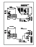
WIRING DIAGRAM for electrical connection details and jumper
settings. Place jumpers to select desired output format. Once
installed, the compass must be calibrated to correct for local
magnetic distortions caused by nearby structures. To calibrate the
compass, follow the procedure outlined below.
1.2 SETUP
Operating mode may be set with simple jumpers or customized with
software commands via serial connection. Settings are retained when
power is removed.
1.2.1 COMPASS CALIBRATION
1. Remove cover from compass. Press and hold CALIBRATE button
for 5 seconds. The CALIBRATE indicator will begin to blink. Refer
to WIRING DIAGRAM to locate CALIBRATE button.
2. Slowly rotate vehicle on which compass is mounted. Steer vehicle
in a tight circle and make TWO complete revolutions. Each
revolution should take at least one minute. THE COMPASS MUST
REMAIN LEVEL DURING CALIBRATION.
3. After two complete revolutions, press and hold CALIBRATE button
until indicator stops blinking. Calibration is now complete.
Calibration parameters are retained when power is removed.
4. Replace cover. Use this procedure to recalibrate compass at any
time.
1.2.2 AUXILIARY INPUTS
The 32500 has two special inputs for wind speed and direction and
four auxiliary voltage input channels for connection to other
meteorological instruments like temperature and humidity sensors,
and barometers. For best performance, the sensors should be
installed within 3m (10ft.) of the 32500. Measurements from the
auxiliary input channels are converted to numerical values (0-4000
Full Scale) and sent in the selected serial output string.
For VIN1 and VIN2 full scale input is 1.00 VDC, therefore:
Serial output value = input millivolts x 4
For VIN3 and VIN4 full scale input is 5.00 VDC, therefore:
Serial output value = input millivolts x 0.8
Refer to serial output format drawing and wiring diagram.
1.2.3 JUMPERS
W1 JUMPERS
The two W1 jumpers determine serial output format.
The two jumper positions are designated A and B. Four possible
jumper configurations and associated output format are listed
below. The first three configurations set the 32500 output to a
popular format without further intervention. The last configuration,
SOFTWARE MODE, allows output format and other operating
parameters to be set via a software Command menu. Refer to the
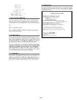
WIRING DIAGRAM for jumper locations. Refer to the SERIAL
FORMAT DIAGRAM for details regarding serial output format.
The SERIAL COMMUNICATION section provides details about
SOFTWARE MODE.
JUMPERS SERIAL OUTPUT FORMAT
NONE
WS WD1 V1 V2 V3 V4 COMPASS WD2
A
RMYT for connection to YOUNG Wind Tracker
B
NMEA sentences
A & B
SOFTWARE MODE
The first 3 format selections override any software commands
given in the above SOFTWARE MODE. See page 4 for detailed
SERIAL OUTPUT FORMAT information.
W2 JUMPERS
The W2 jumper pattern sets the output connection
type. Only one connection type may be used at one time. Refer
to the WIRING DIAGRAM drawing for jumper location and
connection details.


