Version 11.09.2020
HW: CAM(V100)/(V52)
RL4-NAC
P
a
g
e
8
1.6.1.
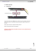
Adjustment
–
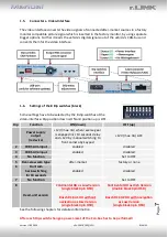
power supply output (dip 1)
If set to
ON
, the video interfaces’ red wire will 12V (max 3A) with engaging the
reverse gear and additionally 10 more seconds delay
for the time of the front camera’s back
-
switching after the reverse gear has been disengaged.
Furthermore, the red wire’s power
supply for the front cam becomes active with manually front camera switching (short press
of the external keypad).
If set to
OFF
, the video interfaces’ red wire will supply per12V ACC (max 3A).
Description of the power supply output: see chapter “Power supply output”.
1.6.2.
Enabling the interface’s video inputs (dip 2
-3)
Only the enabled video inputs can be accessed by switching through the interface’s video
sources. It is recommended to enable only the required inputs. Then the disabled inputs will
be skipped while switching through the video interfaces inputs.
1.6.3.
Rear-view camera settings (dip 5)
If set to
OFF
, the interface switches to factory picture while the reverse gear is engaged to
display factory rear-view camera or factory optical park system picture.
If set to
ON
, the interface switches to its rear-view camera input while the reverse gear is
engaged.
1.6.4.
Activating
–
front camera back-switching (dip 6)
If set to
ON
, the interface switches for 10 seconds from the rear-view camera to the front
camera input after having disengaged the reverse gear. In addition, a manual switch-over to
the front camera input is possible via keypad (short press) from any image mode.
(Attend to correct adjustment of the power supply output (dip1)!
1.6.5.
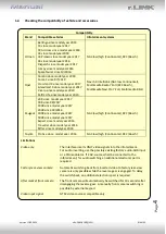
Head unit selection (Dip 8)
Dipswitch 8 is used to set the corresponding Head-Unit version.
Dip switch position ON supports the
Continental "Low Version"
Head-Unit
(Continental Head-Unit with
single
black HSD connector on the back)
Dip switch position OFF supports the:
Continental "High Version"
Head-Unit
(Continental Head-Unit with
double
black HSD connector at the back)
Bosch "Low Version"
Head Unit
(Bosch Head-Unit with a
single
black HSD connector on the back)
Note:
Dip1 and 7 are out of function and have to be set to
OFF
.
After each Dip-switch-change a power-reset of the interface box has to be performed!


