


Version 29.01.2020
HW: CAM (V97)/ (V52)GD
RL3-MBN51
P
a
g
e
10
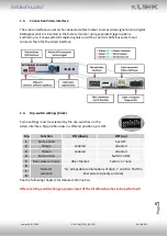
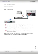
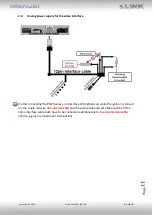
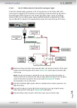
2.3.2.
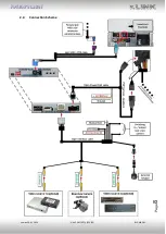
Power and CAN connection
Connect the 10pin power/CAN cable’s female 10pin connector to the 10pin connector of the
interface
Connect the single, yellow wire of the 10pin power/CAN cable to +12V permanent and
stabile power supply.
Connect the single, black wire of the 10pin power/CAN cable to the vehicle’s negative
ground.
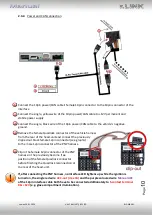
Remove the female Quadlock connector of the vehicle harness
from the rear of the head-unit
and
connect the previously
clipped out black female 12pin connector (see graphic)
to the male 12pin connector of the PNP harness.
Clip in the female 12pin connector of the PNP
harness in the previously become free
position of the female Quadlock connector
before finishing the Quadlock reconnection at
the rear of the head-unit.
If, after connecting the PNP harness, no interface LED lightens up while the ignition is
turned on, the single red wire
ACC-out (max 3A)
and the purple coloured wire
Manual ACC
of the 12pin interface cable both have to be connected additionately to
S-contact
terminal
86s +12V
(e.g. glove compartment illumination).


