Do not use grease or other lubricating products between the
pinion and the rack.
5) Bring another rack element closer to the previous one, using a
piece of rack to put the teeth of both sections in phase.
3.4. ZIPPER ASSEMBLY
2) Support the first rack section on the pinion, correctly leveled,
and place the spacer in the upper part of the slot between the rack
and the gate.
4.2. REGULATION OF THE TRANSMITTED TORQUE
ATTENTION: THE ENGINE IS SUPPLIED WITH THE CLUTCH
CALIBRATED TO THE MAXIMUM, SO THE SCREW MUST BE
TURNED TOWARDS THE LEFT UNTIL THE MOST CONVENIENT
CI ON IS SET.
1) Close the leaf manually.
To increase the torque, turn the screw clockwise.
The intervention threshold of the electronic device depends on
the calibration of the mechanical clutch.
Fig. 9
NB Check that, during the movement of the gate, no element of
the rack comes off the pinion.
4) Move the gate manually, checking that the rack rests on the
pinion, and repeat the operations described in point 3).
3) Move the gate manually, checking that the rack rests on the
pinion, and repeat the operations described in point 2).
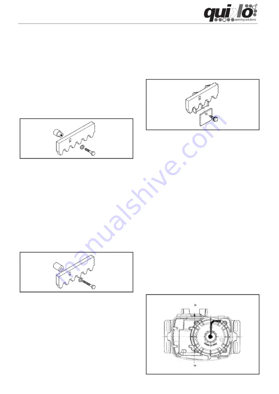
Fig. 10
Move the gate by hand and check that it reaches the mechanical
limit stops correctly. The movement should be smooth and without
friction.
4.1. CONNECTING ELECTRONIC EQUIPMENT
6) Move the gate manually and repeat the fixing operations as for
the first element. Continue until the entire gate is covered.
To calibrate the transmitted force regulation system, use the
screw located on the rotation axis of the electric motor (fig. 10).
1) Assemble the three threaded pins on the rack element, placing
them in the upper part of the slot. This way, slot play will allow for
any necessary adjustments as time goes on.
Attention: before carrying out any type of operation on the
electronic equipment (connections, programming or
maintenance), always disconnect the power supply.
2) Support the first section of rack, correctly leveled, on the pinion
and mark the point where the gate should be drilled. Drill with a 4
mm diameter drill bit and place the 6 x 20 mm self-tapping screw
with the respective reinforcement plate.
To reduce the torque, turn it counterclockwise.
3) Support the first rack section on the pinion, correctly leveled,
and weld the threaded pin to the gate. 4) Move the gate manually,
checking that the rack rests on the pinion, and weld the next two
pins.
1) Close the leaf manually.
4) Bring another rack element closer to the previous one, using a
piece of rack to put the teeth of both sections in phase. 5) Move
the gate
manually and repeat the fixing operations as for the first element.
Continue until the entire gate is covered.
3) Mark the drilling point on the gate. Drill with a 6.5 mm diameter
drill bit and thread with an 8 mm tap. Screw in the bolt.
6) Open the gate manually and weld the three threaded pins.
Continue until the gate is completely covered.
Start the engine and manually stop the gate to check the
engagement of the clutch. Remember that, when this operation is
carried out, the electronic anti-crush device interrupts the opening
movement and reverses the closing movement.
5) Bring another rack element closer to the previous one, using a
piece of rack to put the teeth of both sections in phase.
Attention: do not weld the zipper elements to the spacers or to
each other for any reason (only for steel zippers).
Fig. 8
2) Close the leaf manually.
Fig. 7
3.4.2. STEEL RACK TO SCREW (fig. 8)
3.4.3. NYLON ZIPPER TO SCREW (fig. 9)
3.4.1. STEEL ZIPPER FOR WELDING (fig.7)
4. COMMISSIONING
Machine Translated by Google


