Quietside QVM9 Series Manual Download Page 42


QVM 9 

Series


40


Models : QVM9-090/125/150W1-NG


(UNIT : mm)

No 

Part Code


Part Name 

Q

ty

Material 

Remarks 

C21701155A 

BBR15012041 

Front Cover 

1

SCP1 

QVM9-090/125W1 


C21701221A 

BBR15012042 

〃 

1

SCP1 

QVM9-150W1 

C21701340A 

BBK05011024 

Cabinet 

1

SCP1 

QVM9-090/125W1, 0.8T 


C21701341A 

BBK05011025 

〃 

1

SCP1 

QVM9-150W1, 0.8T 

C21750164A 

BH2505188A 

Base Bracket 

2

SBHG1 

All QVM9 

C20109029B 

BH2505012A 

Flue Exhaust 

1

STS 

All QVM9 

C21606016B 

BH2423034A 

Flue Exhaust Packing 

1

EPDM 

All QVM9 

C21701216A 

BH2505055A 

Combustion Air Intake 

1

PP 

All QVM9 

C21701217A 

BH2505062A 

Combustion Air Intake Plate

1

PP 

All QVM9 

C22203009A 

BH1419007A 

High Limit Fuse 

1


All QVM9, Fuse Type 

C21605023A 

BH2405002A 

Adiabatic Plate 

1

AL+CERAMIC

QVM9-090/125W1, 2T 


C21601042A 

BH2405001A 

〃 

1

AL+CERAMIC

QVM9-150W1, 2T 

10 

C21014139E  NACR1GS20602  Main Controller 

1


All QVM9, KDC-206-3M V1.4 

11 

C22601008A 

BH3101003A 

Expansion Tank 

1


QVM9-090/125W1 


C22602020A 

BH3102010A 

〃 

1


QVM9-150W1 

12 

C21708271A 

BH2507155A 

Heat Exchanger Inlet Pipe 

1

C1220T 

QVM9-090W1 


C21708274A 

BH2507156A 

〃 

1

C1220T 

QVM9-125W1 


C21708311A 

BH2507157A 

〃 

1

C1220T 

QVM9-150W1 

13 

C21213011A 

BH1409002A 

Heating Flow Sensor 

1

NYLON 66 

All QVM9,  φ20 

14 

C21708267A 

BH2507152A 

Air Vent Outlet Pipe 

1

C1220T 

All QVM9 

15 

C20501022A 

BH1101014A 

Circulation Pump Assembly

1


All QVM9, CS-0125V, 115V/60Hz 

16 

C20313022A 

BH0902015A 

3-Way Valve 

1


All QVM9, A3-18-223A, 115V/50/60Hz 

17 

C21708253B 

BH2507087A 

Heating Supply Connection 

1

C3712 

All QVM9 

18 

C21708275A 

BH2507154A 

Air Vent Outlet Connection 

1

C3712 

All QVM9 

19 

C20301006D 

BH2507004A 

Heating Air Vent 

1


All QVM9 

20 

C21708268A 

BH2507143A 

Air Vent Inlet Pipe 

1

C1220T 

All QVM9 

21 

C20901011B 

BH1301010A 

Heating Strainer 

1


All QVM9 

22 

C21708255B 

BH2507097A 

Heating Return Connection 

1

C3712 

All QVM9 

23 

C20307017A 

BH0905006A 

Pressure Relief Valve 

1


All QVM9 

24 

C21899001C 

BH2501224A 

Siphon 

1

PE 

All QVM9 

25 

C21708261A 

BH2507081A 

Heating Outlet Pipe 

1

C1220T 

All QVM9 

26 

C40306019B 

BBXCC087008  Fan Assembly 

1

AL 

QVM9-125/150W1, Without Air Filter 


C40306022B 

BBXCC087009  Fan Assembly 

1

AL 

QVM9-090W1, Including Air Filter 

27 

C21707120C 

BH2501200A 

Orifice 

1

STS 

QVM9-090W1, LNG, 

φ

27.4 


C21707123C 

BH2501203A 

〃 

1

STS 

QVM9-125W1, LNG, 

φ

29.5 


C21707199B 

BH2501204A 

〃 

1

STS 

QVM9-150W1, LNG, 

φ

28.5 

28 

C21707114B 

BH2501170A 

Mixing Chamber Assembly 

1

ALDC 

QVM9-090W1 


C21707115B 

BH2501171A 

〃 

1

ALDC 

QVM9-125W1 


C21707146B 

BH2501172A 

〃 

1

ALDC 

QVM9-150W1 

29 

C21750162A 

BH2501221A 

Mixing Chamber Bracket 

1

SBHG1 

QVM9-090/125W1 


C21750168A 

BH2501220A 

〃 

1

SBHG1 

QVM9-150W1 

30 

C21707116B 

BH2501114A 

Nozzle 

1

C3712 

QVM9-090W1, LNG, 

φ

5.95 


C21707118B 

BH2501116A 

〃 

1

C3712 

QVM9-125W1, LNG, 

φ

6.60 


C21707197A 

BH2501118A 

〃 

1

C3712 

QVM9-150W1, LNG, 

φ

6.30 

31 

C21605026A 

BH2405006A 

Mixing Chamber Packing 

1

CERAMIC 

QVM9-090W1, 5T 


C21605028A 

BH2405007A 

〃 

1

CERAMIC 

QVM9-125W1, 5T 


C21605040A 

BH2405008A 

〃 

1

CERAMIC 

QVM9-150W1, 5T 

32 

C40306016A 

BBXCC088001  Burner Assembly 

1

Metal Fiber 

QVM9-090W1, 150 X 100 


C40306018A 

BBXCC088002 

〃 

1

Metal Fiber 

QVM9-125W1, 200 X 100 


C40306024A 

BBXCC088003 

〃 

1

Metal Fiber 

QVM9-150W1, 200 X 133 

33 

C21002008A 

BH1401007A 

High Limit Sensor 

1


All QVM9, MS-1P, Manual, Bi-Metal Type  

34 

C20701079A 

BH1201004A 

Ignition Transformer 

1


All QVM9, DK-304, 115V/50/60Hz 

35 

C21002016A 

BH1401004A 

High Limit Sensor 

1


All QVM9, MS-1P, Automatic, Bi-Metal Type 

36 


Flame Observation Port 

1

MICA 

All QVM9 

Parts List


Summary of Contents for QVM9 Series

Page 1: ...arranty Does Not Cover 1 Installations by other than qualified heating contractors 2 Installations of equipment for other purposes than those intended by the instructions supplied with this equipment...

Page 2: ...guish any open flame y Do not try to light any appliance y Do not touch any electrical switch do not use any phone in your building y Immediately call your gas supplier from a neighbor s phone Follow...

Page 3: ...16 y Installation of the Flue 18 y Draining Condensed Water 21 y About the FR 5 Thermostat 22 y Installation of the Thermostat 23 y Using the Thermostat FR 5 24 y Test Operation and Checks 28 y Routin...

Page 4: ...QVM 9 Series 2 Model QVM 9 090W1 NG 125W1 NG 150W1 NG Identifying the Components...

Page 5: ...THE BURNER BY HAND 5 TURN KNOB OF GAS VALVE TO OFF POSITION 6 WAIT A FEW MINUTES TO CLEAR OUT ANY GAS THEN SMELL FOR GAS INCLUDING NEAR THE FLOOR IF YOU DON T SMELL GAS GO TO THE NEXT STEP 7 TURN KNOB...

Page 6: ...ater level in the heat exchanger is continuously monitored to prevent the water heater from operating if there is no water or a restricted flow of water in the unit The water heater will be automatica...

Page 7: ...he Check Lamp is LIT during the operation it means that the gas supply has run out Check the lamp frequently For other troubleshooting see page 35 and 38 CAUTION Do not use the water heater for other...

Page 8: ...prolonging the life of the unit Setting the water heater temperature at 120 F will reduce the risk of scalds Some states require settings at specific lower temperatures The table below shows the appr...

Page 9: ...it instantaneously The modulating gas burner allows water to heat up evenly as it is being used The QVM 9 will continue to heat the water until the source or sources are shut off This on demand use al...

Page 10: ...cally restart In cold weather climates manual resets could cause freeze damage 12 Safety Protection During Power Outages When the power fails the gas valve is automatically shut down 13 Automatic Fill...

Page 11: ...lways monitored and the water heater will not start when there is no water in the exchanger 8 Thermostat Safety Protection If the thermostat fails combustion will be stopped and the gas supply is auto...

Page 12: ...a heating cycle The unit will switch over from heating to provide domestic hot water When the use of hot water is stopped The unit automatically converts back to the heating mode If hot water is to b...

Page 13: ...thermostats drain valve and relief valve As the gas water heater is to be installed indoors they shall not be installed outdoors such as in the porch Do not install water heater on a combustible wall...

Page 14: ...e brass male connectors below the unit Allow fittings to cool before attaching to unit Use only approved coupling unions with O rings to attach field piping to unit The heating pipe should be 3 4 and...

Page 15: ...plumbing supplier Mixing type valve Controls the desired hot water temperature and ensures constant hot water temperature in the faucets accuracy 2 Ensures safety through the built in anti burn scald...

Page 16: ...ater heater WARNING For safe operation an ample supply of air must be provided for proper combustion and ventilation in accordance with the national fuel gas code ANSI Z223 1 or CAN CGA B149 1 or B149...

Page 17: ...ce the risk if location in such an area cannot be avoided Flammable items pressurized containers or any other potential fire hazardous articles must never be placed on or adjacent to the water heater...

Page 18: ...ockage These are parts of the gas supply system not the water heater Vent blockage may occur during ice build up or snow storms When local codes require a main manual shut off valve outside the water...

Page 19: ...mmediate and severe damage to the gas valve and its internal pressure regulating device and could result in property damage and or personal injury Set DIP switch 1 to the ON position priority fill The...

Page 20: ...urn back to the water heater Do not place the outdoor termination kit in an area where discharge gases will be directed towards evergreen shrubbery Assemble the flue using the following illustration a...

Page 21: ...connection of the air supply hose must be sealed by the wire clamp to prevent any air loss In the connection of the flue duct and the flue elbow an O ring must be inserted to prevent leaks Do not use...

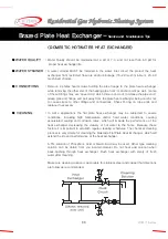
Page 22: ...QVM 9 Series 20 Schematic of SCF 9 Installation Installation of the Flue...

Page 23: ...inimum diameter of 1 2 inch is to be used IMPORTANT The siphon reservoir in the water heater should be filled with water If no water is available do not operate the water heater The condensed water sh...

Page 24: ...ore than others could find that setting the thermostat to the water temperature sensing function will provide the best comfort We suggest trying them both The Air Temperature Mode The QVM 9 hydronic h...

Page 25: ...ge colored stranded wires from unit to the 2 screws located on the FR 5 thermostat 4 Mount the back plate to the wall using either of the above techniques depending on the construction of the wall Rec...

Page 26: ...QVM 9 Series 24 Thermostat Model FR 5 Using the Thermostat FR 5...

Page 27: ...ion in this mode set the temperature control below 104 Rad The unit will stop but the freeze prevention function will stand by 1 Press the Away From Home Saving button The room temperature will be ind...

Page 28: ...emperature will be indicated on the temperature display and the Set Temperature lamp and In Use light will go on 2 Turn the Set Temperature dial to select the desired room temperature the temperature...

Page 29: ...t recommended to use this unit for making hot beverages 1 If the water heater cannot run due to a failure in the temperature control call for service The two wires at the back of the room thermostat m...

Page 30: ...of gas does not match the one specified on the unit rating plate modification and re adjusting will be required Consult your heating dealer or a qualified technician with the gas utility company Test...

Page 31: ...heater refer to page 21 Turn 1 DIP switch to ON position Trial Operation mode Install the room thermostat FR 5 Power lamp will flash 1 second ON 1 second OFF during trial operation Open the manual wat...

Page 32: ...t water provided from the water heater If the power supply to the water heater is shut off after the test operation completely drain water from the system heating hot water to prevent possible freeze...

Page 33: ...H OR OTHER STATIC CREATING MATERIAL TO CLEAN DUST AND CARBON DEPOSITS FROM HEATING SURFACES AND VENT SUCH DEPOSITS ARE FLAMMABLE AND MAY BE IGNITED BY STATIC ELECTRICITY USE A METAL BRUSH TO MINIMIZE...

Page 34: ...ub or faucets Check the pressure of the incoming water supply If the pressure is lower than the minimum hot water pressure install a separate pressurizing pump 6 Check for external contamination Stop...

Page 35: ...me applications the flat plate heat exchanger may be subjected to severe conditions including high temperature and or hard water conditions causing accelerated scaling and corrosion rates which will i...

Page 36: ...ties from the system When heating performance is decreased clean the filter by removing clip washing out and re inserting the filter Replace the clip CAUTION THE WATER FLOWING OUT OF THE PRESSURE RELI...

Page 37: ...er 5V DC 09 Fan RPM Failure y Fan failure y Check speed control y Check fan for operation Input voltage 7 40V DC Red Black wires 10 Air Pressure Switch Failure y Fan failure y Air flow switch failure...

Page 38: ...QVM 9 Series 36 Wiring Diagram Error Codes FR 5 Thermostat DIP S W Setting on Main Controller Wiring Connecters...

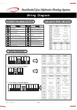
Page 39: ...37 QVM 9 Series Wiring Diagram...

Page 40: ...pipe If the pipe is clogged contact the unit installer Clean the heating strainer Check the circulation pump After removing the cause press the HEAT ON button again Low or no gas pressure Contact for...

Page 41: ...39 QVM 9 Series Models QVM9 090W1 NG 125W1 NG 150W1 NG Exploded Views...

Page 42: ...Air Vent 1 All QVM9 20 C21708268A BH2507143A Air Vent Inlet Pipe 1 C1220T All QVM9 21 C20901011B BH1301010A Heating Strainer 1 All QVM9 22 C21708255B BH2507097A Heating Return Connection 1 C3712 All...

Page 43: ...M9 125W1 C21708382A BH2507041A 1 STS304 QVM9 150W1 48 C21708252A BH2507057A Gas Control Valve Outlet Connection 1 ALDC All QVM9 49 C21708269B BH2507164A Heat Exchanger Outlet Pipe 1 C1220T QVM9 090W1...

Page 44: ...put BTU hr 40 000 78 300 50 000 100 000 60 000 117 400 Max Temperature Setting o F 176 Continuous DHW production 45F delta T gpm 3 5 4 4 5 3 Continuous DHW production 60F delta T gpm 2 6 3 3 4 0 Conti...

Reviews: