


QVM 9
Series
6
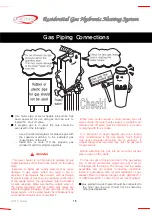
■ The heating water supply piping should be 3/4″. An isolation (ball-type) valve should be installed before the
piping is connected to the units.
■ Black iron piping or 3/4″ flexible connector (approved by the local authorities for gas) should be used for gas
piping.
■ Do not use Teflon tape for gas pipe connections.
■
Install a gas drip leg at the unit.
■ Gas piping should be kept at the required distance away from any electric lines and the main service
panel(check with local authorities).
Items
Distance
(inches)
1. Distance from electric lines
6″
2. Distance from electric heaters and electric panels
24″
3. Distance from flue pipes and outlets
12″
■ Install the ball valve(cut-off valve) before connecting the gas piping to the unit (Allow space for the lever’s full
movement, install valve as close to the unit as possible).
■
After the gas pipe has been completed, all connections must be checked with soapy water.
Note!
- Do not
test for gas leaks by pumping air-pressure into the line without first disconnecting the gas line to the unit.
Pressuring the unit will void the manufacturers warranty. Releasing this pressure into the unit will cause
immediate and severe damage to the gas valve and its internal pressure regulating device and could result in
property damage and/or personal injury.
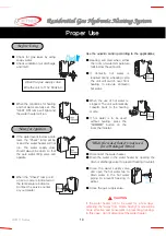
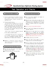
Set DIP switch #1 to the ON position(priority fill). The pump will run continuously and the low water
level sensor will be automatically turned on/off for 1-minute intervals. Ensure that all water valves to
unit are open.
Twist open(approx. 1/2 turn) the manual air vent until a steady stream of water is flowing and the
spurting of air stops. – Open all other bleed valves on system.
Close the manual air vent (any remaining air will bleed out of the system by means of the automatic
air vent).
After the quick fill is complete, reset the #1 DIP switch to the OFF position.
If the heating flow sensor stays ON, stop the pump by resetting the #1 DIP switch(switch ON, then
back OFF again).
Remove strainer, check for debris, clean and refit.
Ensure that system pressure has been bled off using the pressure / relief valve.
NOTE !
-
While in the Quick Fill mode, the power indicator light, on the FR-5 thermostat will flash : 1-second
ON and 1-second OFF.
Standard Gas Piping
Consult with your gas provider to determine the proper diameter of gas pipe. This will
vary due to input capacity, the number of elbows and length of pipe.
Trial operation Quick-Fill
STEP 1
Gas Piping Connections
STEP 2
STEP 3
STEP 4
STEP 5
STEP 6
Summary of Contents for QVM9 Series
Page 4: ...QVM 9 Series 2 Model QVM 9 090W1 NG 125W1 NG 150W1 NG Identifying the Components...
Page 22: ...QVM 9 Series 20 Schematic of SCF 9 Installation Installation of the Flue...
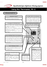
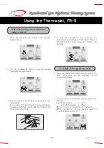
Page 26: ...QVM 9 Series 24 Thermostat Model FR 5 Using the Thermostat FR 5...
Page 39: ...37 QVM 9 Series Wiring Diagram...
Page 41: ...39 QVM 9 Series Models QVM9 090W1 NG 125W1 NG 150W1 NG Exploded Views...


