


Residential Gas Hydronic Heating System
Residential Gas Hydronic Heating System
Residential Gas Hydronic Heating System
Residential Gas Hydronic Heating System
35
35
35
35
QVM 9
Series
Troubleshooting
Troubleshooting
Troubleshooting
Troubleshooting
Error Code
Error Code
Error Code
Error Code
Cause
Cause
Cause
Cause
Troubleshooting
Troubleshooting
Troubleshooting
Troubleshooting
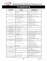
01) Overheat
•
Clogged / Reduced flow in heating
system
•
Circulating pump failure
•
Check strainer clean if required
•
Check system for flowrate
•
Check pump for operation
–
115V AC = 1
Amp
02) Low Water Level
•
No water in system / Pump failure
•
No make up water supply
•
Water fill valve failure
•
Check system / Check pump
•
Check system
•
Check system 5V DC- input signal
03 / Ignition Failure
•
Check ignition transformer
•
Check high limit switch / fuse
•
No gas supply
•
Air pressure switch tripped
•
Input 115V AC
•
N/C contacts
•
Check gas connection
•
Check gas valve
•
Check tube for connection
•
Check flue for blockage
04 / Flame Sensor
•
Low gas pressure
•
Fan failure / Airflow pressure
switch
•
Check gas valve pressure operated
•
Check gas pressure
•
Check fan for operation
•
Check switch, flue for obstruction
05 / Heating Sensor Wire
Disconnected
•
Check molex connection
•
Re - connect
06 / Heating Sensor Short
Circuit
•
Non-applicable
07 / Hot Water Sensor
Wire Disconnected
•
Non-applicable
08 / Hot Water Sensor
Short Circuit
•
Sensor failure
•
Check voltage @Pin #19&8 on 21Pin
connector, main controller 5V DC
09 / Fan RPM Failure
•
Fan failure
•
Check speed control
•
Check fan for operation. Input voltage 7
–
40V DC. Red-Black wires
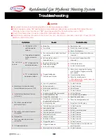
10 / Air Pressure Switch
Failure
•
Fan failure
•
Air flow switch failure
•
Blocked flue
•
Excessive wind gusts
•
Check fan for operation
•
Check tube connection
•
Check voltage 5V DC
•
Check flue for blockage
•
Check flue termination - relocate
11 / Water level Detection
Failure
•
Check water fill valve
•
Voltage 5V DC
12 / Flame Failure
•
Low gas pressure
•
Fan failure / Air flow sensor
•
Blocked flue
•
Check gas pressure
•
Check gas valve
•
Check fan for operation
•
Check tube on air flow sensor
•
Check air flow sensor
–
5V DC
•
Check flue for obstruction
13 / Heating Water Switch
Failure
•
Faulty switch
•
Check voltage
–
5V DC on Pin #10 on 13
pin and Pin #17 on 21 pin connectors
14 / Gas Alarm (Optional)
•
Check if connected (Red / Black
wire)
•
Re
–
connect
•
Check gas supply
•
Check voltage 5
–
20V DC
15 / Micom Failure
•
Check connection from t-stat to unit
•
Replace t-stat or micom controller
16 / Mechanical Overheat
•
Pump motor overheat
•
Fan motor overheat
•
Check for pump operation 115V AC,
approx 1A (dependent on flow rate)
•
Check fan for operation
•
Check rotation
17 / DIP Switch Setting
•
Incorrect settings
•
Check setting especially for 090/125/150
boilers


