Residential Gas Hydronic Heating System
Residential Gas Hydronic Heating System
Residential Gas Hydronic Heating System
Residential Gas Hydronic Heating System
QVM 9
Series
14
14
14
14
Installation
Installation
Installation
Installation
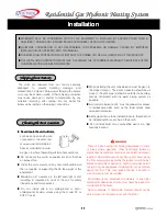
For safe operation, an ample supply of air must be
provided for proper combustion and ventilation in
accordance with the national fuel gas code, ANSI Z223.1
or CAN/CGA-B149.1 or B149.2(latest editions) or
applicable provisions of the local building codes. An
insufficient supply of air may result in a yellow, luminous
burner flame, carboning or sooting of the finned heat
exchanger, or create a risk of asphyxiation. Do not
obstruct the flow of combustion and ventilation air.
NEVER OPERATE THE HEATER UNLESS IT IS VENTED
TO THE OUTDOORS AND HAS ADEQUATE AIR SUPPLY
TO AVOID RISKS OF IMPROPER OPERATION, FIRE,
EXPLOSION OR ASPHYXIATION.
Lime scale accumulation can reduce the life of the
equipment, reduce efficiency and waste fuel. Boiler failure
due to lime or scale buildup voids the warranty.
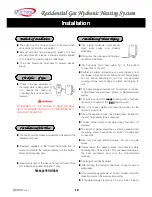
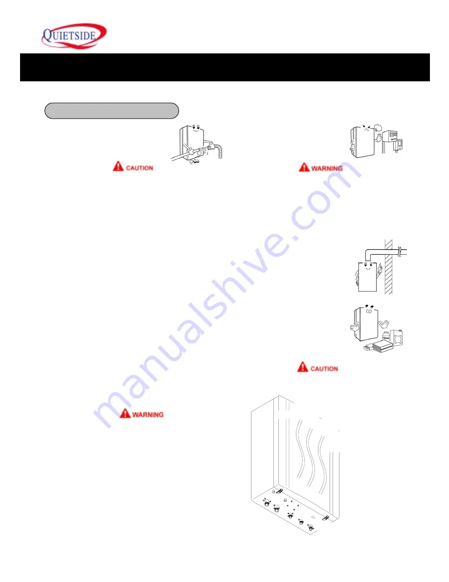
■
Piping for heating and hot water
should be cleaned before
connecting to the unit.
■
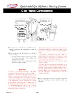
The boiler needs a large quantity of air for
combustion, the specified vent must be installed. If
not incomplete combustion will occur and prevent
normal operation of the boiler.
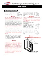
■
The boiler should be at least 24
”
away from electric appliances.
The boiler is set up for AC 115V
60Hz.
More than 24"
Only for AC115V, 60Hz
■
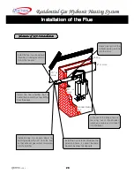
Flue made of schedule 40 PVC
or stainless steel.
■
To facilitate the discharge of
exhaust gas, the flue should be
installed with fewest possible
bents and curves. The flue should
have a diameter larger than that of
the flue of the boiler.
■
Do not place flammable items
near the boiler. Never place
combustibles such as vinyl
bags, matches, thinner, etc on
boiler
The flow of combustion air to the boiler must not be
obstructed.
The boiler area must be kept clear and free from
combustible materials, gasoline and other flammable
vapors and liquids.
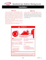
Check the metal tag on the relief valve and compare it to
the heater
’
s rating plate. The pressure rating of the relief
valve must not exceed the working pressure shown on the
rating plate of the heater. In addition, the hourly BTU rated
temperature discharge capacity of the relief valve shall not
be less than the input rating of the heater.
NO VALVE IS
TO BE PLACED BETWEEN THE RELIEF VALVE AND
TANK. DO NOT PLUG THE RELIEF VALVE.
The drain line connected to this valve must not contain a
reducing coupling or other restriction and must terminate
near a suitable drain to prevent water damage during
valve operation. The drain line shall be installed in a
manner to allow complete drainage of both the valve and
line.
DO NOT THREAD, PLUG OR CAP THE END OF THE
DRAIN LINE.
Precautions for Installation
Precautions for Installation
Precautions for Installation
Precautions for Installation
Read first before connection to power supply
Read first before connection to power supply
Read first before connection to power supply
Read first before connection to power supply
Remove Rubber Grommet
Remove Rubber Grommet
Remove Rubber Grommet
Remove Rubber Grommet
to connect line
to connect line
to connect line
to connect line
voltage
voltage
voltage
voltage
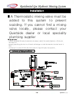
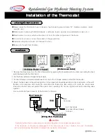
Low Voltage
(Thermostat Wire)
Orange
Orange
Blk
Red
Black
White
Green
Low Voltage
(for optional gas alarm)
Gray Wire
(to live voltage)

