quhwa VP-700A Instruction Manual Download Page 9


B connect to the 1,2,3,4,5,6 connection terminals of the indoor monitor A.


Same connection between monitor B and C.

3. The 5,6 connection terminals of outdoor camera connect to the lock; the  

    “

”,“

” connection terminals of indoor monitor connect to the power of DC 15V. 

7

.

Operation Instruction

1. Press CALL button of outdoor camera and graceful rings will be heard from 

    indoor monitor and images of visitors will be seen. Then you can talk with 

    them and see them just by pressing TALK button of the indoor monitor. The 

    talking time can last about 120 seconds. Press TALK button to end a 

    conversation at any time. 

2. Press UNLOCK button to release the door.

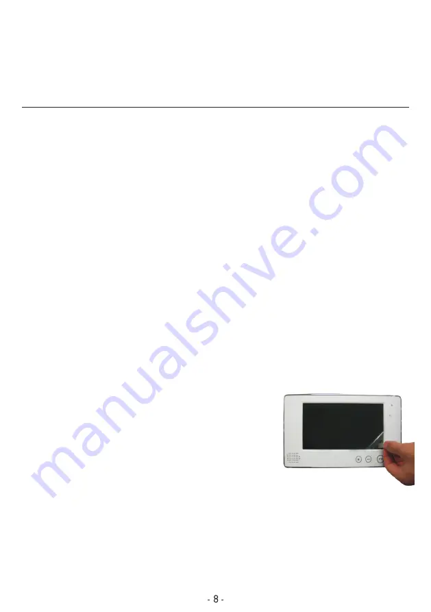
9. In order to reach the best images result, please take off the protective coating 

    of the screen.

10. The kit including three cards. If need more user 

    cards, please do according to the following steps:

Firstly

, use the adding card to touch the ID card 

Secondly

, use the user card to touch the same area.

Thirdly

, use the adding card to touch the same area. Then the new user card is 

    added successfully. At most 1000 user cards can be added.

11. If need to delete any user cards, please do according to the following steps:

    touching zone of the outdoor station.

3. Pressing MONITOR button can monitor the outside. The monitoring time lasts 

    about 40 seconds.

4. Press the MONITOR button of the indoor monitor, then press the TALK button 

    to talk to the visitor. After talking, press TALK again to end the conversation.

5. The brightness, and chroma can be adjusted by using the button or knob to 

    reach the best result.

6. Ring volume adjustable by switch.

7. 14 polyphonic melodies for option by using the button at the side of monitor.

8. Talking volume adjustable by using knob.

Firstly

, use the delete card to touch the ID card touching zone of the outdoor 

   station.

Summary of Contents for VP-700A

Page 1: ...Instruction Manual COLOR VIDEO DOOR PHONE KITS VP 700A ID ...

Page 2: ... Camera Performance Data 2 3 Indoor Monitor Performance Data 3 4 Indoor Monitor Installation 4 5 Outdoor Camera Installation 4 6 Notices of Wiring Diagram 5 7 Operation Instruction 8 8 Accessories 9 9 Notices 9 CONTENT PAGE ...

Page 3: ...lled door release function 7 Monitoring the outside of house 8 Fourteen polyphonic melodies 9 Ring volume talking volume chroma and brightness adjustable 10 Enclosed 15M cable and one adapter for DIY market Call Name Plate Infrared Light Camera Microphone Speaker 2 Outdoor Camera Performance Data 1 IR distance more than 4M 2 Automatic gain control 3 Working temperature 20 C 50 C 4 Resolution CMOS ...

Page 4: ...tandby 0 5W working 10W 7 Illumination intensity 2 luces 8 Visual angle 92 wide angle 9 Working temperature 5 C 40 C 10 Relative humidity 10 90 RH Parameter Screen Size Resolution Active Area Pixel Size Screen Figure Dimension Unit Inch Dot mm mm mm 169 4 W X 100 H X 5 7 D 0 107 W X 0 37 H 154 1 H X 86 58 V 480 X 3 X 234 7 0 Specifications Performance Parameter 11 Indoor monitor dimension 232 W X ...

Page 5: ... 2 3 Take off the name plate for marking family name or room name and then fix the screws of the back cover Picture 1 4 Install the outdoor camera at a height of 1 4m 1 7m and make sure it 2 1 Bracket 4 Indoor Monitor Installation 1 Fix the bracket of the video indoor monitor on the wall with screws Picture 1 2 Hang the monitor on the bracket after finishing the wire connection Plug the tenclosed ...

Page 6: ...door monitor connect to DC15V power accordingly 1 The 7 8 9 10 11 connection terminals of the indoor monitor connect to the 6 Notices of Wiring Diagram The video door phone kit includes 15 meters wire If wanting extension to 15 2 50 meters please use the 5 0 5mm wire If wanting extension to 50 100 meters 2 please use the 5 0 75mm wire avoiding the direct sunshine or rain Picture 2 5 Fix the bracke...

Page 7: ... option 1 The 1 2 3 4 7 connection terminals of the outdoor camera connect to the 7 8 9 10 13 connection terminals of the indoor monitor A The 5 6 connection terminals of outdoor camera connect to the lock 2 The other group of 1 2 3 4 connection terminals of the indoor monitor A connect to the 1 2 3 4 connection terminals of the indoor monitor B Same connection between monitor B and C 3 The connec...

Page 8: ...r B 2 The 7 8 9 10 11 12 13 connection terminals of the indoor monitor A connect to the 1 2 3 4 5 6 connection terminals of the Second camera controller IN DC Power 3 4 5 2 1 5 6 3 4 2 1 3 4 2 1 1 5 A B IN 1 2 3 4 5 6 DC 15V 7 8 9 10 11 12 13 14 1 2 3 4 5 6 DC 15V 7 8 9 10 11 12 13 14 1 2 3 4 5 6 DC 15V 7 8 9 10 11 12 13 14 Indoor Monitor B option Indoor Monitor A Indoor Monitor C option Outdoor C...

Page 9: ...r cards please do according to the following steps Firstly use the adding card to touch the ID card Secondly use the user card to touch the same area Thirdly use the adding card to touch the same area Then the new user card is added successfully At most 1000 user cards can be added 11 If need to delete any user cards please do according to the following steps touching zone of the outdoor station 3...

Page 10: ...itting the units 5 Image could be illegible if the camera is shined by strong light 6 If you use internal wireless communication systems image may be fuzzy because of interference from radio waves ID card user card adding card delete card deleted successfully 12 The adding card and delete card are set well already If the user loses the adding card or delete card he or she can re program a new sett...

Page 11: ......

Reviews: