background image

Page 14

9.2  Mid range driver

No recone kit is available for the mid range so if a fault developes the unit will need to
be replaced.
Remove the 4 self tapping wood screws using a posidrive no.2 screwdriver. Take out
the unit and disconnect the two wires, noting which colour goes to which terminal. If
on removing the 4 screws that hold the mid range there is any difficulty in removing
the unit do not try to force a blade between the cabinet and mid range, but use a
small narrow bladed screwdriver in one of the screw holes to gently lever out the unit.
Connect the new mid range and re assemble into the cabinet. Do not ovetighten the
4 screws.

9.3  Bass driver and bass driver recone.

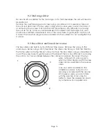
The bass drivers are held in by four M5 machine screws. Remove the screws in the
order shown below using a 4mm hex driver  The drivers are heavy so hold the driver by
the frame when removing the last screw. Remove the bass driver, using a screwdriver in
one of the screw holes to gently lever out the driver if there is any difficulty in removing
the unit. Do not force a blade between the cabinet and driver. Disconnect the two

wires, noting which colour goes to
which terminal. Replace with the new
driver and re-assemble in the reverse
order.

A recone unit is available for the
VH3208 bass driver. Instruction for
reconing is included with the recone
kit. However, unless you are familar
with the practise of reconing it is
better to have the speaker reconed
by someone who is experienced.

1

3

4

2

Summary of Contents for VH3208

Page 1: ...V V V V H H H H 3 2 0 8 User Manual Quested Monitoring Systems ...

Page 2: ...s 6 4 2 1 Definitions 6 4 2 2 Passive Operation 7 4 2 3 Bi Amped Operation 8 4 2 4 Tri Amped Operation 9 4 2 5 Cable 10 5 Technical specification 10 6 Guarantee 11 7 Appendix 11 7 1 Accessories 11 7 2 Spares 11 8 Line Drawing 12 9 Driver replacement procedure 13 9 1 Tweeter tweeter diaphragm 13 9 2 Mid range driver 14 9 3 Bass driver bass driver recone 14 Page 1 ...

Page 3: ...lease read this manual which we have kept as concise as possible it really will help you and covers important safety considerations The VH3208 is a 3 way passive monitor and can be used sofit mounted or free stand ing They are suitable for use as main monitors in smaller control rooms or as mid field reference monitors in larger rooms The bass drivers are fully magnetically shielded and a fully ma...

Page 4: ...s There are no international agreed limits and different countries have different limits measured in differing ways IT IS THEREFORE IMPORTANT THAT THE USER ESTABLISHES THE RECOM MENDED AND IN SOME TERRITORIES LEGAL LIMITS THAT ARE IN PLACE As a guide the table below shows the levels that are acceptable in the majority of Western Europe and the US Canada SPL dB A Listening time per day 90 8 hours 9...

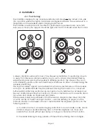
Page 5: ...positioning Placing the cabinet against a wall will reinforce the bass performance of the speaker and up to an additional 3dB may be obtained Placing the monitors in a corner will further reinforce the bass performance and gains of up to 6dB may be achieved but be very careful about siting the monitors in a room corner because it can excite stand ing waves and create an unpleasant boominess The sp...

Page 6: ...t and the axis of the speakers chould cross between 0 5 and 1 meter behind the listening position Page 5 The height of mounting the speaker is equally as important The correct height should result in the axis being at ear level when the engineer is sitting in his normal position at the console ...

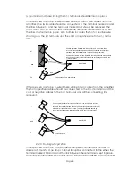
Page 7: ...units On the VH3208 the input to each section of the internal crossover is available on separate terminal connections to facilitate a number of different wiring options BI WIRED This is a wiring option when running the monitors in the passive mode Here the single channel amplifier has a pair of twin cables running between its output terminals and the input terminal tray of the monitor Generally th...

Page 8: ...tronic crossover THE VH3208 CANNOT BE RUN IN THE 3 WAY ACTIVE MODE 4 2 2 Passive operation These monitors can either be installed with a single twin cable 2 twin cables bi wired or 3 twin cables tri wired It is recommended that the monitors are installed bi or tri wired This will make a small improvement in sound quality by minimising distortions produced by voltage losses associated with the inte...

Page 9: ... should be connected to the either the terminal marked Mid or Hi and the link between these terminals kept in place Another channel should be connected to the terminal marked Lo and the links AMPLIFIER Passive operation but with tri wired connection 3 twin cables are run from the amplifier One wire should be connected to the terminal marked Lo the second to the terminal marked mid and the final wi...

Page 10: ...o and Links between Lo Mid removed Amplifier 1 should drive the mid hi The connection from this amplifier should be to either the terminal marked Mid or Hi and the link between the terminals should be kept in place Amplifier 2 will drive the lo The connection from this amplifier should be to the terminal marked Lo and the link between terminals marked Mid Lo should be removed With both twin cables...

Page 11: ...nge 1 x 75mm 3 softdome High Frequency soft dome 1 x 28mm 11 8 Maximum SPL 110dB C Sensitivity 92dB at 1 watt at 1 meter Frequency Response 45Hz 20kHz 2dB Nominal Impedance 8Ω Connectors Triple pair gold plated binding posts for 4mm banana or bare wire allowing connection through the passive crossover to the individual sets of drivers Crossover Multipole network utilizing polypropylene capacitors ...

Page 12: ...ipment has not been taken apart or tampered with in any way other than described in the service manual for the adjustment and replacement of user accessible items The guarantee does not cover a Damage during transit b Damage to diaphragms cones and other speaker parts as a result of the over driving of the monitors or by faulty installation or connection c Damage caused by incorrect installation o...

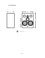
Page 13: ...Page 12 485mm 19 612mm 241 4 324 123 4 432 17 Acoustic Centre 8 Line Drawing ...

Page 14: ...bly and replace with the new diaphragm The Ferrofluid has the appearance of oil and is dark brown in colour and should cover about 1 3 of the coil If there is less than this then additional Ferrofluid should be added This can be obtained from your dealer distributor or directly from Quested The ferrofluid reference is It should be noted that ferrofluid is best added as shown in the digram below Th...

Page 15: ... screws 9 3 Bass driver and bass driver recone The bass drivers are held in by four M5 machine screws Remove the screws in the order shown below using a 4mm hex driver The drivers are heavy so hold the driver by the frame when removing the last screw Remove the bass driver using a screwdriver in one of the screw holes to gently lever out the driver if there is any difficulty in removing the unit D...

Reviews: