LTE-A Module Series
UMTS<E EVB R2.0 User Guide
UMTS<E_EVB_R2.0_User_Guide 17 / 44
4
EVB Components Application
This chapter mainly describes the following EVB components application:
⚫
Power supply
⚫
UMTS<E TE-A connector
⚫
USB connector
⚫
Audio connector
⚫
(U)SIM connector
⚫
SD card connector
⚫
UART connector
It also provides information about the buttons, switches, status indicators and test points to help
customers use the EVB.
4.1. Power Supply (J201/J502)
The UMTS<E EVB R2.0 can be powered by an external power adapter through connected with the
power jack (J201) or USB Type-C receptacle (J502) on the EVB. Please pay attention to the voltage value
of the power adapter, and 5V/2A is recommended. The power adapter is designed to be connected to a
step-down converter (U201), which can convert the supplied voltage into proper voltage (VBAT) for the
module.
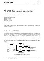
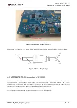
The following two figures show the simplified power supply block diagram and the EVB power supply
interface.
J201
S201
Power
supply
Power
switch
Step-down converter
U201
TPS54319
J103
VBAT
Power supply for
the module
1.8V
3.3V
U301
LDO
U303
LDO
J502
USB Type-C
interface
2.85V
U302
LDO
Power supply for
Wi-Fi modules
Power supply for
SD Card
Figure 7: EVB Power Supply Block Diagram

