LTE-A Module Series
UMTS<E EVB R2.0 User Guide
UMTS<E_EVB_R2.0_User_Guide 9 / 44
“*” means eMMC function is under development, and the eMMC component is not mounted.
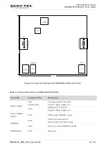
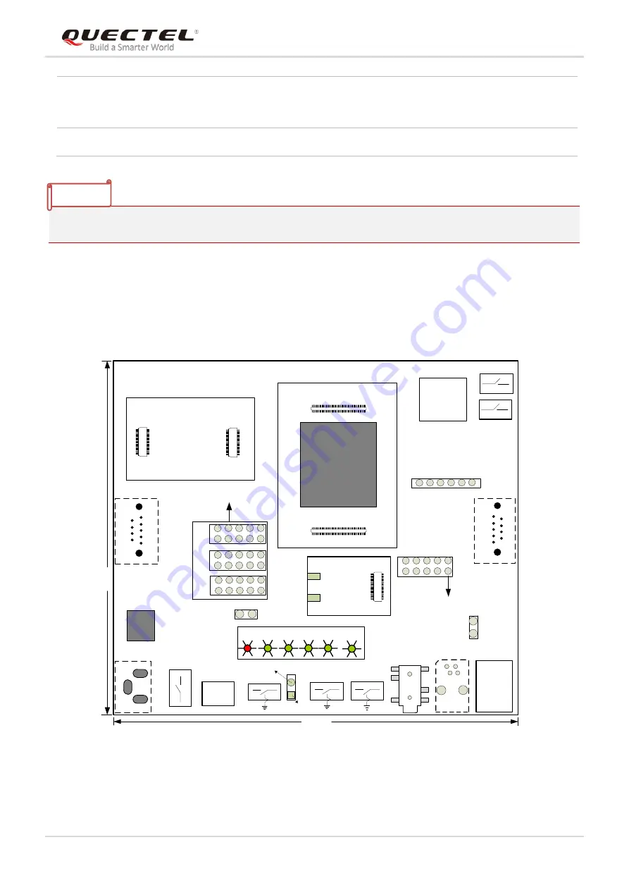
2.2. Component Placement of UMTS<E EVB R2.0
C
O
M
1
(
M
A
IN
)
J502
S201
S303
USB Type-C
J702
Power ON/OFF
Switch
RESET
D209
J401
S302
PWRKEY
D205 D207 D208 D206
RESERVED
SD Card
Connector
GND
J
3
0
2
J103
(U)SIM Card
Connector
J402
C
O
M
2
(
D
B
G
)
VBAT
J805
J902
J901
60 Pins
60 Pins
J102
J101
100 Pins
100 Pins
J701
J806
J804
S901
S301
PWRDWN_N
J501
60 Pins
J803
J601
Earphone
Test Points
TE-A of the Module
Codec board
Handset RJ11
Connector
J602
Test Points
146.4
1
1
5
.0
D215
S902
J603
J403
GND
PAD
Thermal GND PAD
5V
GND
G
N
D
Figure 1: Component Placement of EVB Top Side (Unit: mm)
Switches and Buttons
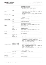
Power ON/OFF Switch(S201), PWRDWN_N (S301), PWRKEY (S302),
RESET (S303), PCM Function Switch (S901), SD Card & eMMC*
Function Switch (S902)
Physical Characteristics
Size: 146.4mm × 115.0mm
NOTE


