Smart LTE Module Series
Smart EVB G2 User Guide
Smart_EVB_G2_User_Guide 20 / 59
4
Interface Applications
This chapter describes the hardware interfaces of Smart EVB G2, shown as follows:
Power supply interfaces
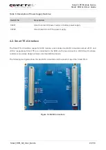
Smart TE-A interface
LCM interfaces
Touch panel interfaces
Camera interfaces
USB interface
Audio interfaces
(U)SIM interfaces
UART interfaces
SD card interface
Emergency download interface
It also provides information about flashlights, sensors, vibrator, buttons, status indication LEDs and test
points to help customers use the Smart EVB G2.
Power Supply Interfaces (J0201/J0202)
4.1.
The Smart EVB G2 can be powered by an external 5.0V DC power adapter. Connect the DC power
adapter to the power jack (J0201) and then the step-down converter (DC-to-DC converter), which is used
to regulate the 5.0V DC power supply voltage to 4.2V for powering up the module.
The Smart EVB G2 can also be powered by a Li-polymer battery through the battery connector J0202 on
the board.
The following figure shows the simplified power supply block diagram of Smart EVB G2.


