background image


GNSS  Module  Series 

                                                                                                                                LC29D  EVB  User  Guide 

LC29D_EVB_User_Guide                                                                                                                            8  / 22 


3


Connector  Applications 


3.1. 

Tape-B USB Connector 

 
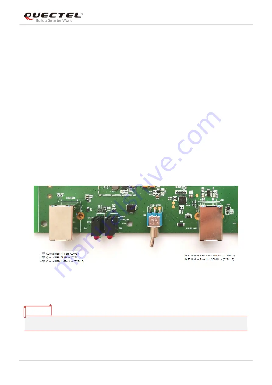
Both Type-B USB connectors can supply power for the EVB. The power supply current of EVB cannot be 
lower than 2A.   
 
EG25 

USB AT Port

 is mainly used for the account configuration of RTK. 


Enhanced COM Port

 is mainly used to configure LC29D module and firmware upgrade. 


Standard COM Port

 is mainly used for LC29D module NMEA output.   

EG25 USB Connector

USB TO UART Connector


Figure 2: Type-B USB Connector 


Before using the EVB, please install the USB driver.   


NOTE 

Summary of Contents for LC29D EVB

Page 1: ...LC29D EVB User Guide GNSS Module Series Rev LC29D_EVB_User_Guide_V1 0 Date 2020 07 02 Status Released www quectel com ...

Page 2: ...E INFORMATION PROVIDED IS BASED UPON CUSTOMERS REQUIREMENTS QUECTEL MAKES EVERY EFFORT TO ENSURE THE QUALITY OF THE INFORMATION IT MAKES AVAILABLE QUECTEL DOES NOT MAKE ANY WARRANTY AS TO THE INFORMATION CONTAINED HEREIN AND DOES NOT ACCEPT ANY LIABILITY FOR ANY INJURY LOSS OR DAMAGE OF ANY KIND INCURRED BY USE OF OR RELIANCE UPON THE INFORMATION ALL INFORMATION SUPPLIED HEREIN IS SUBJECT TO CHANG...

Page 3: ...GNSS Module Series LC29D EVB User Guide LC29D_EVB_User_Guide 1 22 About the Document History Revision Date Author Description 1 0 2020 07 02 Brooke WANG Initial ...

Page 4: ... Antenna Connector 9 3 3 SD Card Connector 9 3 4 U SIM Card Connector 10 3 5 Switches and Buttons 10 3 6 Odo Connector 12 3 7 Operation Status Indication LEDs 13 3 8 Test Points 14 4 Firmware Download 15 4 1 Firmware Download in Normal Working Mode 15 4 2 Firmware Download in Host Mode 15 5 Instructions for the use of RTK 17 5 1 RTK account configuration 17 5 2 Steps to use RTK 18 6 Module Calibra...

Page 5: ...e Index TABLE 1 INTERFACES OF LC29D EVB 6 TABLE 2 SWITCHES AND BUTTONS 11 TABLE 3 PIN DESCRIPTION OF J104 12 TABLE 4 OPERATION STATUS INDICATION LEDS 13 TABLE 5 PIN DESCRIPTION OF J302 14 TABLE 6 ARGUMENTS 17 TABLE 7 RELATED DOCUMENTS 21 TABLE 8 TERMS AND ABBREVIATIONS 21 ...

Page 6: ...NNECTOR 8 FIGURE 3 ANTENNA CONNECTOR 9 FIGURE 4 SD CARD CONNECTOR 9 FIGURE 5 U SIM CONNECTOR 10 FIGURE 6 SWITCHES AND BUTTONS 11 FIGURE 7 J104 TEST POINTS 12 FIGURE 8 OPERATION STATUS INDICATION LEDS 13 FIGURE 9 J302 TEST POINTS 14 FIGURE 10 QGNSS CONFIGURATIONS 15 FIGURE 11 QGNSS CONFIGURATIONS 16 FIGURE 12 EVB PLACEMENT DIRECTION 19 ...

Page 7: ...d with the product If not so Quectel assumes no liability for customers failure to comply with these precautions Ensure that the use of the product meets the national safety and environmental regulations and is allowed in the country and in the environment required Keep away from explosive and flammable materials The use of electronic products in extreme power supply conditions and locations with ...

Page 8: ...D_EVB_User_Guide 6 22 2 General Overview 2 1 Top View of the EVB The following figure illustrates the top view of LC29D EVB A B C D E F G H J K I L M N O P Q R Figure 1 Top View of LC29D EVB Table 1 Interfaces of LC29D EVB SN Part No Description ...

Page 9: ...S401 EG25 RESET button H J403 EG25 module antenna connector I U401 EG25 module J J101 Power supply and EG25 USB interface K D403 EG25 status and network indication LED L D104 Power indication LED M S101 Power switch ON OFF N J201 Power supply Enhanced COM Port LC29D module Standard COM Port EG25 module O S203 DL LC29D module RTK EG25 module P S201 Standby mode control Q D301 1PPS and TXD1 Indicati...

Page 10: ...supply current of EVB cannot be lower than 2A EG25 USB AT Port is mainly used for the account configuration of RTK Enhanced COM Port is mainly used to configure LC29D module and firmware upgrade Standard COM Port is mainly used for LC29D module NMEA output EG25 USB Connector USB TO UART Connector Figure 2 Type B USB Connector Before using the EVB please install the USB driver NOTE ...

Page 11: ...connector connect a passive or active GNSS antenna EG25 antenna connector connect a 4G antenna LC29D Antenna Connector EG25 Antenna Connector Figure 3 Antenna Connector 3 3 SD Card Connector The data received by the SD card and Standard COM Port are the same SD Card Connector Figure 4 SD card Connector ...

Page 12: ... Connector If the U SIM card is not inserted and the LC29D RTK account is not configured the SD card and Standard COM Port cannot receive data U SIM Card Connector Figure 5 U SIM Connector 3 5 Switches and Buttons The following figure illustrates the switches and buttons of the EVB ...

Page 13: ...l be used when configure LC29D module and firmware upgrade RTK LC29D UART1 is connected to EG25 and will be used when LC29D module gets RTCM data S201 NSTANDBY Long press press and hold the NSTANDBY button to enter standby mode and release the button to exit from standby mode Short press press and then release the NSTANDBY button to reset the module S301 BOOT Press and hold the BOOT button during ...

Page 14: ...C29D_EVB_User_Guide 12 22 3 6 Odo Connector 1 2 3 4 5 6 7 8 Figure 7 J104 test points Table 3 Pin Description of J104 SN Signal I O Description 1 5 NC 6 WHEELTICK DI Odometer wheel tick input 7 FWD DI Forward Backward signal input 8 GND Ground ...

Page 15: ...US Indicate the module operating status L2 NETLIGHT Flicker slowly 200 ms High 1800 ms Low Network searching Flicker slowly 1800 ms High 200 ms Low Idle Flicker quickly 125 ms High 125 ms Low Data transfer is ongoing Always high Voice calling L3 POWER EVB power indicator L4 LC29D_PWR LC29D module power indicator L5 1PPS Flash successful fix Extinct no fix L6 TXD Flash the module is turned on succe...

Page 16: ... 4 5 6 7 8 9 10 Figure 9 J302 test points Table 5 Pin Description of J302 SN Signal I O Description 1 RXD1 DI Receive data 2 VCC_3 3V PO 3 3V power output 3 TXD1 DO Transmit data 4 GND Ground 5 RTS1 DO Request to send 6 1PPS DO One pulse per second 7 CTS1 DI Clear to send 8 I2C_SCL OD I2C clock 9 VDD_EXT PO 1 8V power output 10 I2C_SDA OD I2C data ...

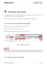
Page 17: ...download in both normal working mode and host mode 4 1 Firmware Download in Normal Working Mode Step 1 Connect J201 to the computer with a Type B USB cable Step 2 Switch S203 to DL and power on the EVB Step 3 Run the QGNSS and then configure the tool as shown below Enhanced COM Port a b d c e UPG bin Figure 10 QGNSS Configurations Please make sure the module is in full on mode before downloading f...

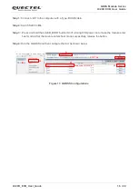
Page 18: ... Step 2 Switch S203 to DL Step 3 Press and hold the LC29D_BOOT button S301 during EVB power on to make the module enter host mode After the module enters host mode successfully release the button Step 4 Run the QGNSS and then configure the tool as shown below Enhanced COM Port a b d c e BOOT bin Figure 11 QGNSS Configurations ...

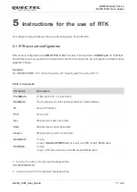
Page 19: ... AT QGNSSPARAM 0 0 ip port quectel_usr quectel_pwd mount_point 1 1 Table 6 Arguments 1 In case of no errors the returned message will be QGNSSPARAM OK 2 In case of any error the returned message will be Parameter Description ProtoMode 0 ntirp protocol 1 tcp protocol DataMode The Tcp protocol is valid 0 Rover Station 1 Base station IP Server IP address Port Server port Usr Ntrip protocol valid user...

Page 20: ...on the EVB Step 3 Configure your RTK account Step 4 Restart the EVB after the RTK account is configured successfully Step 5 Connect Standard COM Port after restart baud rate is 460800bps Step 6 Need to be in an open sky environment to get into the RTK Step 7 When PQTMINS the second parameter of becomes 3 or 4 enter RTK successfully Example PQTMINS 680013 4 31 821291735 117 116094469 63 424977 1 26...

Page 21: ...ation is essential This chapter introduces the calibration of LC29D module 6 1 EVB placement The EVB should be placed as illustrated in the following figure and no movement should happen otherwise the calibration may fail The white arrow is the forward direction of the vehicle and the EVB should be placed horizontally Forward Direction Figure 12 EVB Placement Direction ...

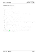
Page 22: ...ibration data PQTMRESETINSCFG 5B 2 Configure DR calibration mode PQTMSETINSPROFILE 2 1 1 5B Step 4 Switch S203 to RTK and start the vehicle Step 5 Keep the vehicle unmoved for at least 30 seconds on a flat road 1 2 tolerance in gravity direction Step 6 Speed at least 5m s open ground 1 minute Step 7 When PQTMINS the second parameter of becomes 2 or 4 the calibration is successful Example PQTMINS 6...

Page 23: ...otocol_Specification LC29D GNSS Protocol Specification 3 Quectel_LC29D_Reference Design LC29D Reference Design 4 Quectel_QCOM_User_Guide QCOM User Guide 5 Quectel_QGNSS_User_Guide QGNSS User Guide Abbreviation Description CNR Carrier to Noise Ratio DI Digital Input DO Digital Output EVB Evaluation Board GNSS Global Navigation Satellite System GPS Global Positioning System LED Light Emitting Diode ...

Page 24: ...GNSS Module Series LC29D EVB User Guide LC29D_EVB_User_Guide 22 22 PO Power Output PPS Pulse Per Second PRN Pseudorandom Noise SV Satellite Vehicle TTFF Time To First Fix UTC Universal Time Coordinated ...

Reviews: