LPWA Module Series
BG95xA-GL&BG950S-GL_TE-B_User_Guide 22 / 24
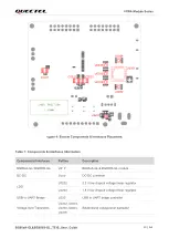
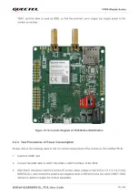
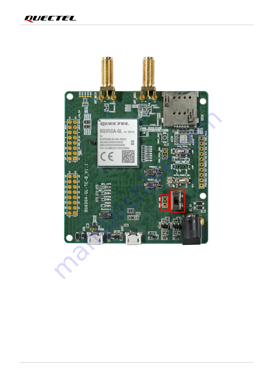
VBAT, and the other is used as GND, so that the external power supply can supply power to the
module separately.
S
0
2
0
1
J
0
2
0
2
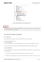
Figure 10: Schematic Diagram of TE-B Before Modification
4.2.3.
Test Procedures of Power Consumption
Please refer to the following steps to test the current consumption of the module on the modified TE-B
:
1. Insert the USIM card.
2. Connect the USB cable to J0301 (the USB-to-UART interface) of the TE-B.
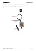
3. After S0201 (the power switch) is turned off, set the output voltage on N6705C to 3.3 V or 3.8 V (only
BG955A-GL), and connect the positive and negative wires of N6705C to the two wires (VBAT, GND)
welded on J0202 to supply the module separately.