background image

GV500MA


User


Manual

TRACGV500UM001

4


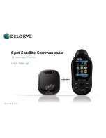
3.4. Device Status LED 

Figure 6. 

GV500MA LED on the Case 

Table 5: Definition of Device status and LED 

Note: 

1 - CELL LED cannot be configured. 

2 - GNSS LED can be configured to turn off after a period of time using the configuration tool 

3 - Fast flashing is about 60ms ON/ 780ms OFF 

4 - Slow flashing is about 60ms ON/ 1940ms OFF 

LED 

Device status 

LED status 

CELL 

(note1) 

Device is searching 

GPRS/EGPRS/LTE

 network  

Fast flashing  

(Note3) 

Device has registered to 

GPRS/EGPRS/LTE

 network. 

Slow flashing 

(Note4) 

GNSS 

(note 2) 

GNSS chip is powered off 

OFF 

GNSS sends no data or data format error. 

Slow flashing 

GNSS chip is searching GNSS info. 

Fast flashing 

GNSS chip has gotten GNSS info. 

ON 

‐ 

11

FCC Statement 

Any Changes or modifications not expressly approved by the party responsible for compliance could void the 

user’s authority to operate the equipment.   

This device complies with part 15 of the FCC Rules. Operation is subject to the following two conditions: (1) 

This device may not cause harmful interference, and  

(2) This device must accept any interference received, including interference that may cause undesired 

operation.   

FCC Radiation Exposure Statement:

This equipment complies with FCC radiation exposure limits set forth for an uncontrolled

environment .This equipment should be installed and operated with minimum distance 20cm between the 

radiator& your body.

3.5. Bluetooth:

The device role of Bluetooth could be Master and Slave. 

When the device role is Slave, the device will provide below services: device information service, 

battery information service, virtual serial port service. Other devices can read or use these 

services after connecting devices. 

When the device role is Master, the device will provide below services: the others devices

can read or use the above services after connecting devices, connect the designated

device to read the data or related information of the designated Bluetooth devices. After

reading the data, the server can be reported to the server by the corresponding message.

NOTE:

The frequency for LTE: 

Band2:1850-1910MHz,Band4:1710-1755MHz,Band5:824-849MHz.

Band12:699-716MHz,Band13:777-787MHz, Band26:814-849MHz.

The LTE module FCC ID: XMR201707BG96.

The frequency for 2G:

GPRS/EGPRS850:824-849MHz

GPRS/EGPRS1900:1850-1910MHz

Summary of Contents for GV500MA

Page 1: ...GV500 User Manual TRACGV500UM001 0 GPSTracker GV500MA User Manual TRACGV500MAUM001 Version 1 01...

Page 2: ...rthermore system validation of this product designed by Queclink within a larger electronic system remains the responsibility of the customer or the customer s system integrator All specifications sup...

Page 3: ...n history 5 1 Introduction 6 1 1 Reference 6 1 2 Terms and Abbreviations 6 2 Product Overview 7 2 1 Description 7 2 2 Parts List 8 2 3 Interface Definition 8 3 Getting Started 9 3 1 Opening the Case 9...

Page 4: ...nual TRACGV500UM001 3 Table Index TABLE 1 GV500MA PROTOCOL REFERENCE 6 TABLE 2 TERMS AND ABBREVIATIONS 6 TABLE 3 PART LIST 8 TABLE 4 DESCRIPTION OF OBD II CONNECTIONS 8 TABLE 5 DEFINITION OF DEVICE ST...

Page 5: ...0UM001 4 Figure Index FIGURE 1 APPEARANCE OF GV500MA 7 FIGURE 2 THE OBD II CONNECTOR ON THE GV500MA 8 FIGURE 3 OPENING THE CASE 9 FIGURE 4 CLOSING THE CASE 10 FIGURE 5 SIM CARD INSTALLATION 10 FIGURE...

Page 6: ...GV500MA User Manual TRACGV500UM001 5 0 Revision history Revision Date Author Description of change 1 00 2018 11 22 Vincent tang Initial...

Page 7: ...icated power management algorithms System integration is straightforward as complete documentation is provided for the full featured Track protocol The Track protocol supports a wide variety of report...

Page 8: ...iption GV500MA is based on the OBD II interface GNSS vehicle tracking device compact design and easy to install GV500MA contains a 5PIN micro USB connector an internal GPRS EGPRS LTE antenna two inter...

Page 9: ...D II connector are shown in following figure Figure 2 The OBD II connector on the GV500MA Table 4 Description of OBD II Connections Index Description Comment 1 reserved 2 reserved 3 NC No connect 4 GN...

Page 10: ...2 15 reserved 16 PWR External DC power input 8 32V 3 GettingStarted 3 1 Opening the Case Insert the triangular pry opener into the gap of the case as shown below push the opener up until the case unsn...

Page 11: ...013 3 2 Closing the Case The step of closing case is shown as following Figure 4 Closing the Case 3 3 Installing a SIM Card Open the rubber plugandInsert the SIM card into the holder as shown below Fi...

Page 12: ...device must accept any interference received including interference that may cause undesired operation FCC Radiation Exposure Statement This equipment complies with FCC radiation exposure limits set...

Reviews: