Maestro A2200-A, User Manual
The Maestro A2200-A User Manual is an essential guide for operating and troubleshooting this advanced product. Accessible for free download from manualshive.com, this comprehensive manual equips users with step-by-step instructions and valuable insights, ensuring a seamless experience with their Maestro A2200-A device.
Share
Download


Reviews:
No comments
Related manuals for A2200-A

GPS 175
Brand: Garmin Pages: 95

CAREU U1 Lite(WR)
Brand: S&T Pages: 28

NVX430BT
Brand: Jensen Pages: 89

AQUAMAP 80 Series
Brand: Garmin Pages: 36

Approach S1
Brand: Garmin Pages: 12

NUVI 285W
Brand: Garmin Pages: 12

Qube3
Brand: Navman Pages: 50
CNE-ST02BB
Brand: Canyon Pages: 62

GPSMAP 2008
Brand: Garmin Pages: 124
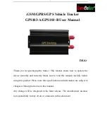
GPS103-A
Brand: Coban Pages: 19
GPS105
Brand: Coban Pages: 24

TZ-VN06
Brand: AVL Pages: 54

FindnSecure FS-65
Brand: EMBARC Pages: 52

GPS 2
Brand: Tractive Pages: 46

LGG100
Brand: Javad Pages: 62

JNSGyro-2T
Brand: Javad Pages: 78

S4
Brand: SONASONIC Pages: 10

eXtreme BT-Q818X
Brand: Qstarz Pages: 28


