background image

GL500 User Manual


3. Getting Started 


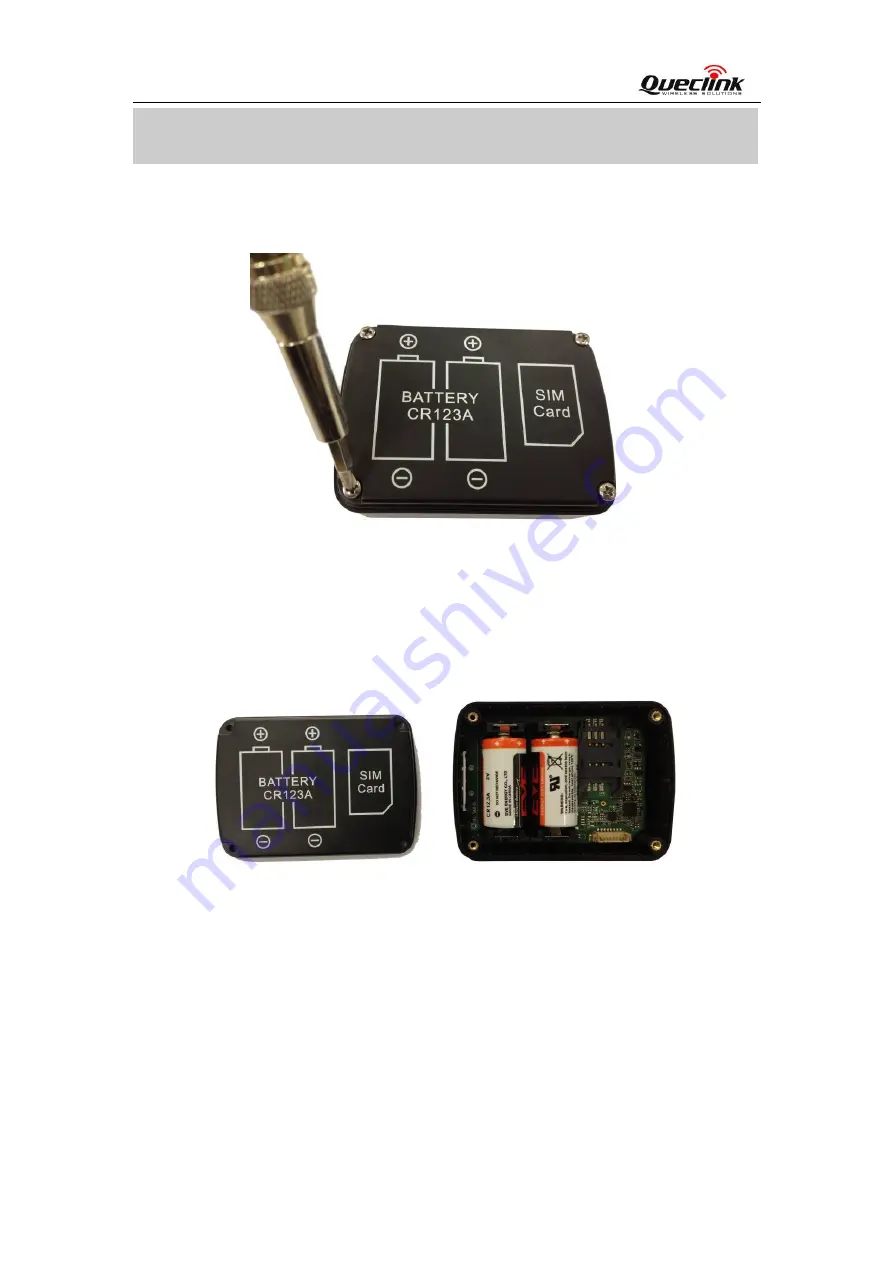
3.1. Opening the Case 


Figure 3. 

Opening the Case 

Use the Screwdriver to remove the screws, and then open the case.   

3.2. Closing the Case 


Figure 4. 

Closing the Case 

Place the cover in the correct position as shown in upon figure. Please note the battery 

direction and SIM Card direction, and then tighten the screws with a Screwdriver. 

3.3. Installing a SIM Card   

Open the case and ensure the unit is not powered (unplug the internal battery). Slide the 

holder right to open the SIM card. Insert the SIM card into the holder as shown below with 

the gold-colour contact area facing down taking care to align the cut mark. Close the SIM 

card holder. Close the case. 

TRACGL500UM001


- 11 - 

Summary of Contents for GL500

Page 1: ...GV300 User manual GSM GPRS GPS Tracker GL500 User Manual TRACGL500UM001 Revision 1 01 sales eddywireless com...

Page 2: ...dation of this product designed by Queclink within a larger electronic system remains the responsibility of the customer or the customer s system integrator All specifications supplied herein are subj...

Page 3: ...ew 8 2 1 Check Parts List 8 2 2 Parts List 9 2 3 Interface Definition 9 3 Getting Started 11 3 1 Opening the Case 11 3 2 Closing the Case 11 3 3 Installing a SIM Card 11 3 4 Installing the Internal Ba...

Page 4: ...ual Table Index Table 1 GL500 Protocol Reference 7 Table 2 Terms and Abbreviations 7 Table 3 Parts List 9 Table 4 Description of 8 PIN Connections 10 Table 5 Definition of Device status and LED 14 TRA...

Page 5: ...Figure 2 The 8 PIN connector on the GL500 10 Figure 3 Opening the Case 11 Figure 4 Closing the Case 11 Figure 5 SIM Card Installation 12 Figure 6 Backup Battery Installation 12 Figure 7 GL500 Status...

Page 6: ...GL500 User Manual TRACGL500UM001 6 Revision History Revision Date Author Description of change 1 00 2012 6 11 Cid Xu Initial 1 01 2013 6 3 Tony Pei Add the direction of GL500 placed...

Page 7: ...System Integrators can easily setup their tracking systems based on the full featured Track protocol This device complies with Part 15 of the FCC Rules Operation is subject to the following two condi...

Page 8: ...2 Product Overview 2 1 Check Parts List Before starting check all the following items have been included with your GL500 If anything is missing please contact your supplier Figure 1 Appearance of GL50...

Page 9: ...23A Battery GL500 Data Cable Optional GL500 MCU Download Kit Optional 2 3 Interface Definition The GL500 has an 8 PIN interface connector It contains the connections for power RS232 MCU Interface etc...

Page 10: ...escription of 8 PIN Connections Index Description Comment 1 CHARGER_IN External DC power input 5V 2 NC Not connected 3 BB_RXD BB UART RXD 4 BB_TXD BB UART TXD 5 MCU_RESET MCU CHIP RESET SIGNAL 6 BKGD...

Page 11: ...n figure Please note the battery direction and SIM Card direction and then tighten the screws with a Screwdriver 3 3 Installing a SIM Card Open the case and ensure the unit is not powered unplug the i...

Page 12: ...nal Backup Battery Figure 6 Backup Battery Installation There have 2pcs internal CR123A battery for GL500 Insert the battery into the holder as shown in upon figure please note that the polarity mark...

Page 13: ...lly the Status LED will start work detail description in the next section Blue GPS Red PWR Green GSM Figure 7 GL500 Status LED 3 6 Direction of GL500 Placed The side with label should towards sky to e...

Page 14: ...owered off OFF GPS sends no data or data format error Slow flashing GPS chip is searching GPS info Fast flashing GPS Blue GPS chip has gotten GPS info ON Battery voltage is lower than 0 OFF Battery vo...

Reviews: