® MVT
Copyright © 2012 Qube Inc. All rights reserved.
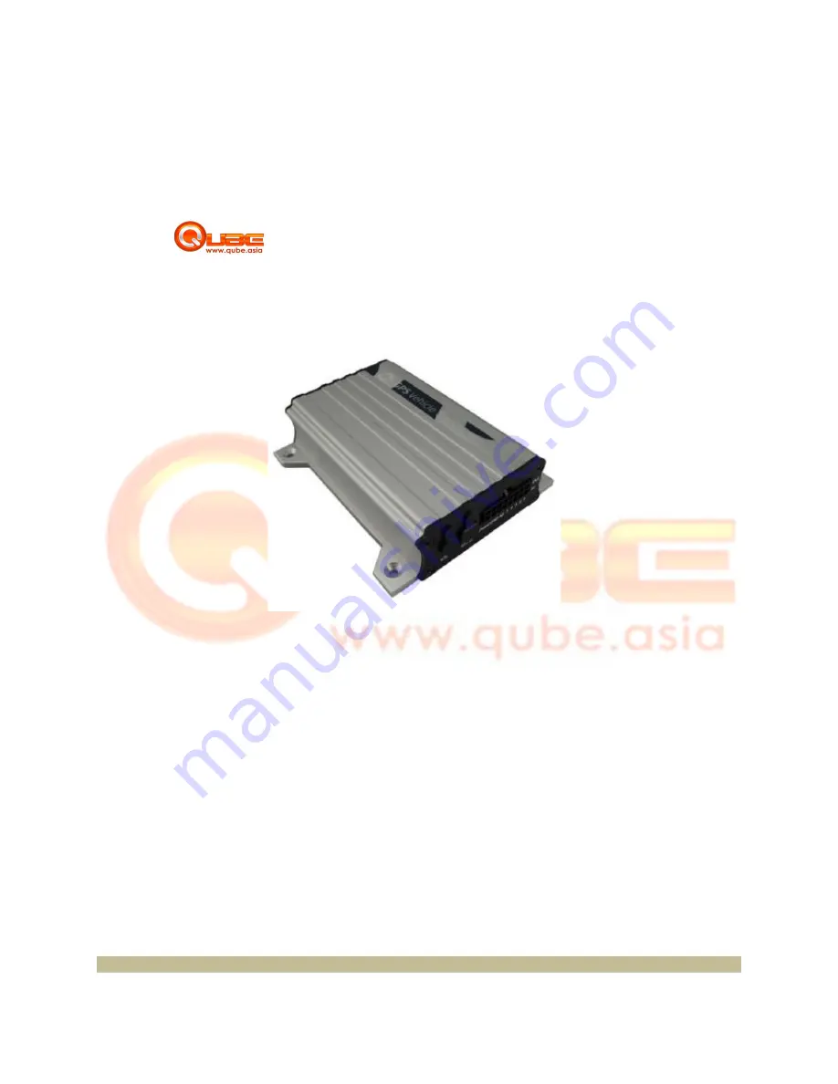
MVT GPS Vehicle Tracker
User Guide V 1.0
GPS Vehicle Tracker
Page
1
Page 1: ... MVT Copyright 2012 Qube Inc All rights reserved MVT GPS Vehicle Tracker User Guide V 1 0 GPS Vehicle Tracker Page 1 ...
Page 2: ...ications 6 5 4 Track by Calling 7 6 Installation 8 6 1 Install I O Cable 9 6 1 1 Power GND PIN7 PIN8 9 6 1 2 Digital Input PIN1 PIN2 PIN3 Negative Triggering 9 6 1 3 Digital Input PIN4 PIN5 Positive Triggering 9 6 1 4 Output PIN9 PIN10 PIN11 PIN12 PIN13 9 6 2 Install GPS GSM Antenna 10 6 3 Install Microphone and Speaker Optional 10 6 4 Mount the Qube GPS Tracker Unit 10 Copyright 2012 Qube Inc All...
Page 3: ...when SOS button is pressed GPS Blind Area Alarm o Report when Qube GPS Tracker enters exits no GPS area Geo Fence Alarm o Report when Qube GPS Tracker Enters or Exit pre defined borders Low Battery Alarm o Report when backup battery s voltage is below 3 5V Speeding Alarm o Report when Qube GPS Tracker speeds higher than the pre set values Impact Alarm o Alarm when Qube GPS Tracker detects impact o...
Page 4: ...umidity 5 95 Work Time 43 hours in power saving mode and 10 hours in normal mode LED 2 LED lights to show GPS GSM and other status Button 1 SOS and 1 power on off Microphone Optional Memory 4MB Sensor Motion sensor Impact sensor GSM Frequency GSM 850 900 1800 1900MHz GPS Chip Latest GPS SIRF Star III chipset GPS Sensitivity 159dB Positioning Accuracy 10 meters 2D RMS I O 5 Digital Input 2 positive...
Page 5: ... into the card holder with the chip module facing to the connectors on PCB Replace the cover and screw it in Copyright 2012 Qube Inc All rights reserved and Accessories Main Unit with Battery not included www qube asia GSM LED Microphone Speaker GPS Antenna USB Port PIN Power I O that the SIM has not run out of credit test using phone Turn off the power before installing the SIM Card Unscrew and r...
Page 6: ...fore installation Press and hold the Power On Off button for 3 5 seconds to turn on off the GPS Unit One button is pressed or input is active Flashing Blinking every 0 1 second Initializing or back up battery is low on and 2 9 sec off Qube GPS Tracker has a GPS fix on and 2 seconds off Qube GPS Tracker unit has no GPS fix A call is coming in a call is being made Flashing Blinking every 0 1 second ...
Page 7: ...JUNE 20 15 25 Date Time in YYMMDD HH MM A GPS Fixed GPS Status Indicator A Valid V Invalid 23 GSM Signal 23 GSM Signal 40Km h Speed 40Km h Kilometer Hour 56 Battery Power 56 Battery Power Balance http maps google com maps f q hl en q 14 612531 121 033403 ie UTF8 z 16 z 16 iwl oc addr om 1 Latitude 14 612531 Longitude 121 033403 Google Maps Web Link Click the link to get the location via Google map...
Page 8: ...e triggering for detecting status of vehicle door or ACC 6 AD1 Blue 10 Bits Resolution Analog Inputs 0 6V DC Detection It can be used to connect with temperature fuel sensor etc 7 GND Black Ground 8 POWER Red DC In power source Input Voltage 9V 36V 12V Suggested 9 OUT1 Yellow Output1 It can be used to connect with relay for engine immobilization Low voltage 0V when effective and open drain OD when...
Page 9: ...e Triggering 6 1 4 Output PIN9 PIN10 PIN11 PIN12 PIN13 Copyright 2012 Qube Inc All rights reserved QUBE QUBE Qube Qube Power GND PIN7 PIN8 Black and Power Red wires to the battery of the vehicle Digital Input PIN1 PIN2 PIN3 Negative Triggering Digital Input PIN4 PIN5 Positive Triggering Output PIN9 PIN10 PIN11 PIN12 PIN13 2012 Qube Inc All rights reserved Page 9 ...
Page 10: ...e directional make sure they are facing up and lying as flat as possible Secure them in place with glue or zip ties Note Do not shield or cover the GPS antenna with any objects containing metal 6 3 Install Microphone and Speaker Optional 6 4 Mount the Qube GPS Vehicle Tracker unit If mounting required there are 4 screw holes on the Qube GPS Tracker 2 along either side that act as fixing points to ...