Quattroflow 150s Operating And Installation Instruction Download Page 12


QF150S; edition 2016-05; page 12 of 19   


4. Maintenance/Servicing of the QF 150S 

 
Due to the robust construction the Quattroflow pump are widely maintenance-free. The ball bearings 
do not need any extra lubrication. 
 
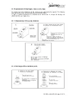
The diaphragms, valves and o-rings should be checked in regular intervals and if needed they has to 
be replaced (Service kit diaphragm-valves-o-rings: PSKITQF15MU). We recommend the following 
maintenance intervals for the different pump parts: 
 
Component Maintenance 

interval 

Action 

Elastomer parts 
(diaphragm, valves, o-
rings) 

1000 h operating hours, 
at least once a year 

Replacement of the elastomer 
parts (order no. PSKITQ15) 

Shaft-bearing-cap unit  

1000 h operating hours, 
at least once a year 

Replacement of the complete 
unit (kit order no.  
PSKITWLC155) 

Motor 

Pay attention to the maintenance information of the manual of the 
motor 

Coupling 

Pay attention to the maintenance information of the manual of the 
coupling 

Gear 

Pay attention to the maintenance information of the manual of the 
gear 


Depending on the operation conditions (pressure, temperature, flow rate, SIP, etc.) it may be 
necessary to shorten the maintenance intervals for the elastomers significantly. 

 
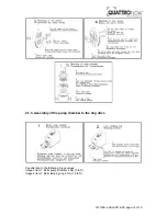
In case that the diaphragm broke it needs to be replaced. Then it is also recommended to check the 
ball bearings. For corrosion reasons or a clearly audible operating noise the parts of the bearing 
service kit should be also replaced. (PSKITWLC155). In general it is recommended to replace the 
elastomer parts whenever the pump chamber is opened. 


Please follow the general guidelines and safety advices when 
handling with chemicals


Disconnect mains supply before opening the pump housing! 

Basically, operations at the pump must be performed during standstill only. The motor 
has to disconnect from the power supply, e.g. by pulling out the power plug or using a 
repair switch, and has to secure against unintentional switch-on. This can be realized by 
a lockable emergency switch. To prevent an accidental re-starting a danger sign should 
be installed.. 


After purging the pump with air there might be a small residual 
amount of fluid inside the pump chamber.  
Flush the pump chamber thoroughly and check the rinse fluid. 
 
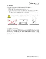
The dismounting and mounting of the pump should be done on a 
rigid table or work bench. Please note: the pump is heavy. 
 
All further warning and safety instruction of chapter 3 has to be 
respected. 


Summary of Contents for 150s

Page 1: ...trol pa manua are of a ope At d the w Orig and tructi 50S Qu Piston ultiple U anel and hou l carefu an appr rating s ttentio warning inal Ins Insta ions aterna Diaph Use using other v ully befo ropria...

Page 2: ...tructions 8 3 5 Safety hints for the operator 8 3 6 Safety instructions for maintenance inspection and mounting operations 9 3 7 Unauthorized reconstruction and spare part usage 9 3 8 Inadmissible mod...

Page 3: ...nd mechanical influences The following storage conditions are recommended Steady ventilated dust and vibration free storage room Ambient temperature between 15 C 59 F and 25 C 77 F with a relative hum...

Page 4: ...cosmetic research centers or plants Examples Solutions containing proteins albumin IgG Clotting factors monoclonal antibodies enzymes vaccines Solutions of polymers or suspensions silicon latex chroma...

Page 5: ...er Prior to each use we recommend to flush the pump with a proper fluid e g water or buffer Prior to the very first use it might make sense to clean and sanitize the pump chamber A commercial caustic...

Page 6: ...r Panasonic 50 W 230V with integrated frequency inverter Speed control Panasonic Digital Control Panel 2 5 Cleaning CIP Depending on the products in contact with the pump and given requirements the cl...

Page 7: ...max 30 min Follow instructions of the autoclave manufacturer Please make sure that the pump chamber is not placed on the clamp ring during the autoclave process The clamp ring should not be loaded dur...

Page 8: ...strictly the safety guidelines of this manual as well as all national and possible internal regulations e g the handling of chemicals like caustic or acid the handling of biological materials the han...

Page 9: ...art up and check the tightness of the pump o Please respect the relevant additional security advices if the pump has been used for aggressive dangerous or toxic liquids e g suitable protective equipme...

Page 10: ...he right tool for the specific application The user operator is responsible to perform a proper method of testing if the pump should be applied for his specific application The chemical and thermal co...

Page 11: ...led personnel Check the electrical cables before connecting to mains supply During all maintenance work it has to be ensured that no explosive atmosphere can arise Appropriate protection equipment is...

Page 12: ...ecessary to shorten the maintenance intervals for the elastomers significantly In case that the diaphragm broke it needs to be replaced Then it is also recommended to check the ball bearings For corro...

Page 13: ...and the valves can be conducted by the operator The following drawings describe it step by step maintenance kit PSKITQF15MU In case of bursting diaphragms by overpressure we advice also to change the...

Page 14: ...05 page 14 of 19 4 1 3 Assembly of the pump chamber to the ring drive Pay attention to the following torque values Image 2 item 1 Bolts pump chamber 4 Nm 3 lb ft Image 2 item 2 Bolt clamping ring 2 N...

Page 15: ...the bearing unit shaft bearing cap unit kit PSKITWLC155 can be conducted by the operator The following drawings describe it step by step Between both coupling halves has to be a gap of 1 mm 0 039 inc...

Page 16: ...truction in discharge line 9 X Pressure line completely or partly clogged diaphragm maybe broken change diaphragm 10 X The diameter of the pipes in suction or pressure line are too small 11 X Check th...

Page 17: ...p Pump rpm motor rpm The flow rates showing at the chart above were ascertained with new diaphragms and new valves under standard conditions after the final assembly of the pump 0 0 5 1 1 5 2 2 5 3 0...

Page 18: ...face approx cm inch 112 17 112 17 Speed range pump rpm 10 3000 10 3000 Connection specification inlet standard Connector 1 4 TC 1 4 TC Flange diameter mm inch 25 25 Internal diameter mm inch 4 7 4 7 C...

Page 19: ...TDK Lambda power supply Designation n a HWS Analog input optional 0 5V 0 10 V Protection class IP54 IP20 switch board Power supply 230V 50Hz 1P optional 110V 60 Hz 1P 85 265VAC 50 60 Hz 8 2 A Housing...

Reviews: