Torridon HS Lite Drive Control Module - Technical Manual
Revision 1.0
©Quarch Technology
Page 14 of 28
Signal Configuration
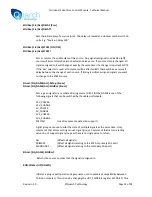
Each signal that is switched by the module is usually assigned to one of the 6 timed sources, S1 – S6.
Each signal can also be assigned directly to ’always off’ (source 0), ‘immediate change’ (source 7) or
‘Always on’ (source 8).
To assign a signal to a control source, write to its CONTROL_REGISTER:
CONTROL_REGISTER Value
Description
0
Signal is always OFF
1
Signal assigned to control source 1
2
Signal assigned to control source 2
3
Signal assigned to control source 3
4
Signal assigned to control source 4
5
Signal assigned to control source 5
6
Signal assigned to control source 6
7
Signal changes with HOT_SWAP
8
Signal is always ON
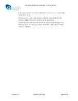
This diagram shows the 9 possible source settings entering the control MUX for a switched signal.
The value of the control register will determine which of the sources are used to control the signal.
When enabled, the hot-swap line will cause the MUX to pass the control signal from that source
through to the switch.
HOT_SWAP
S2
S3
S4
S5
S6
S7 (Immediate Change)
S0 (Always off)
S1
CONTROL REGISTER
Host
mux
S8 (Always on)
Device


