background image


12 


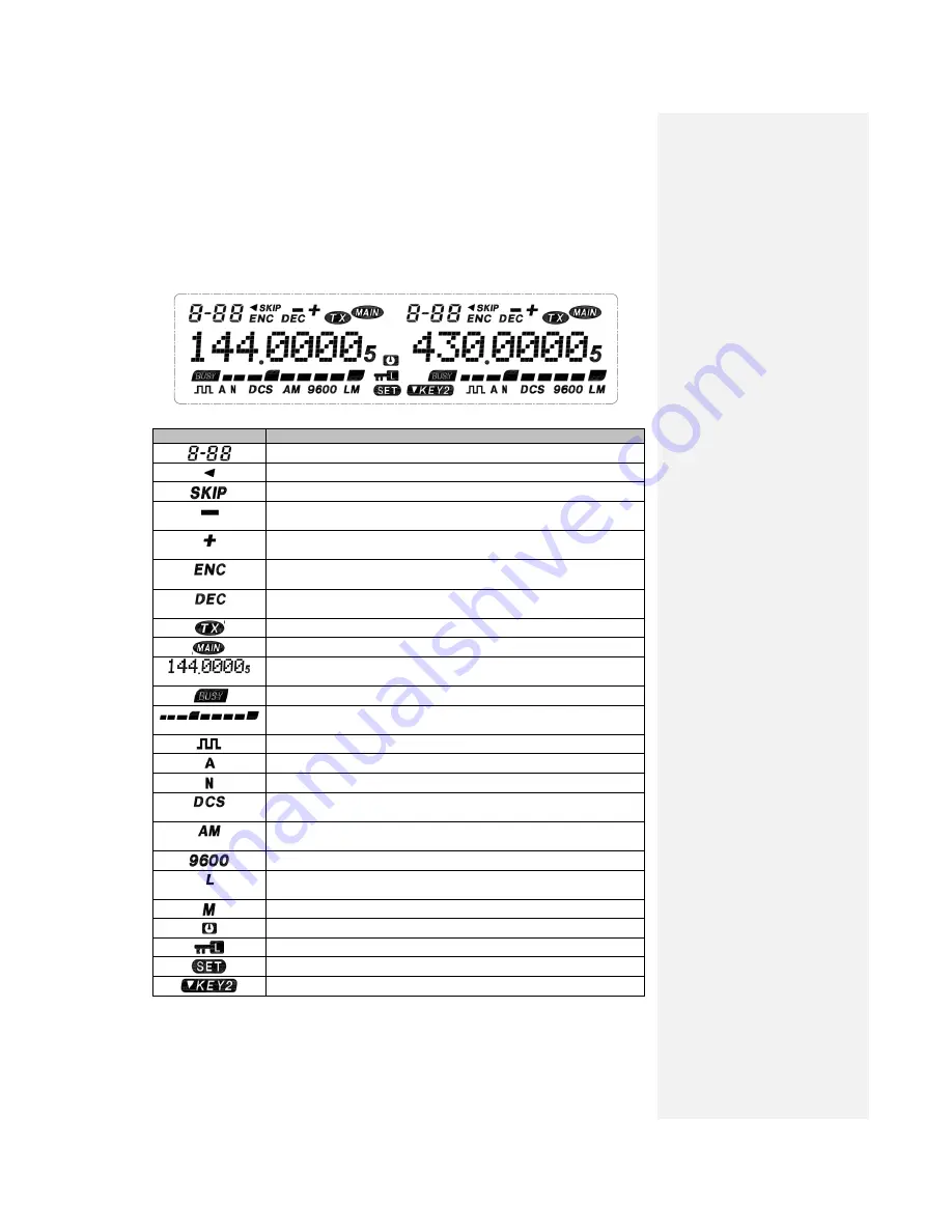
Display Screen 

                    <Left Frequency Band>                                            <Right Frequency Band> 


Icon   

Description   


Displays the number of memory channel and context menu. 


Appears when the frequency reverse function is enabled. 


No definition for this device   


Appears  when  the  transmission  difference  frequency  offset  is  set  as 
negative.   


Appears  when  the  transmission  difference  frequency  offset  is  set  as 
positive.   


Appears  when    transmission  of  CTCSS  (Continuous  Tone  Coded 
Squelch System) is enabled in transmission status.     


Appears when receiving of    CTCSS (Continuous Tone Coded Squelch 
System) is enabled. 


Displays the transmission status. 


Displays that the current frequency band is the main one. 


Displays the operation frequency, name of memory channel and context 
menu. 


Appears in busy signal receiving 

  Displays  the  signal  strength  in  receiving  while  displaying  the  power 

level selected in transmission. 


Appears when the scrambling function is on. 


Appears when the companding function is on. 


Appears in narrow band mode. 


Appears when the DCS function is on. (When the transmission DCS is 
started, it will appear only in the transmission status.) 


Appears when the AM aircraft frequency band is started and the left or 
right band frequency is in the scope of aircraft frequency band. 


No definition for this device 


Appears  when  low  transmission  power  is  used.  (No  icon  display  for 
high transmission power).   


No definition for this device 


No definition for this device 


Appears when the keypad is locked. 


Appears when entering the function menu mode. 


No definition for this device 


Summary of Contents for 9900

Page 1: ...1 Operation Instructions of 9900 Vehicle Mounted Walkie Talkie All rights reserved Quanzhou Baojie Electronics Co Ltd ...

Page 2: ...npowder and detonator The operation of the talkie walkie within 150m 500ft to gunpowder and detonator may lead to explosion In the region of explosion or the region with sign Close dual way radio please turn off your walkie talkie If your vehicle is used to transport gunpowder and detonator be sure they are in the black sealed metal box with internal packing layer Do not transmit signals when you ...

Page 3: ...he battery polarity and voltage of the vehicle Only use the DC power line attached or designated by this company Never insert a metal object into the cooling fan Attention Do not cut down or remove the fuse holder of the DC wire Wrong connection may lead to fume and further fire To ensure passengers safety please use the attached installation support and screw set in the installation of the walkie...

Page 4: ...ncy Band 15 Selection of Operation Mode 16 Transmission 17 Selection of Transmission Power 17 Context Menu Mode Setting of Context Menus 19 Context Menu Setting 19 Operation via Repeater Setting of Repeater 21 Selection of Pilot Frequency 23 Transmission of Pilot Frequency 23 Reverse Frequency Function 23 Memory Channel Memory Channels for Simplex Transmission Receiving with the Identical Frequenc...

Page 5: ... time 34 FM Radio Use of FM radio 35 Auxiliary Functions Power on Information 35 Key Locking 35 Setting of Wide and Narrow Bands W NA 35 Setting of Voice Companding COMP 36 Setting of Voice Encryption SRMR 37 Setting of Frequency Step STEP 37 Setting of Prompt Tone BEEP 38 Setting of Backlight LED 38 Setting of Busy Channel Lock BCL 38 Setting of Transmission Time out Timer TOT 39 Restoration of F...

Page 6: ...e talkie and then insert and tighten the attached the 4 hexagonal screws as shown in Fig 3 Make sure all screws are tightened to avoid loosening of the support or the walkie talkie in vibration of vehicle Utilize the 3 screw grooves at the side rear side of each support to install the main body at a proper inclined angle as shown in Fig 4 5 and 6 Fig 4 Fig 5 Fig 6 Power Line Connection Operation o...

Page 7: ... together with force till the locating plate is locked with a sound of click Operation of fixed radio station If you intend to use the talkie walkie as a fixed radio station you need to buy a independent type of 13 8 DC power supply separately with a suggested continuous current capacity of above 12A Note Do not connect this DC power supply to the AC power socket before all connections are complet...

Page 8: ...ers and other electronic devices and even damage the talkie walkie Without the connection with antenna or other matched load it is prohibited to use the talkie walkie to transmit Otherwise the talkie walkie will be damaged Be sure to connect the antenna to the talkie walkie before transmission and only when the connection is confirmed can the transmission be made All fixed radio stations must be f...

Page 9: ...e For voice communication connect the handheld microphone attached to the MIC socket on the right side of the talkie walkie Please align the RJ12 plastic spring piece upward with the MIC socket till the locking locating plate is locked in place with a sound of click as shown in Fig 10 Fig 10 Get Familiar with the Talkie Walkie Front Panel Left tuning knob DIAL MIC socket Plug of handheld microphon...

Page 10: ... shortly to confirm it V M for switching between VFO frequency mode and memory channel mode Shortly press this key to switch the left band frequency control mode between VFO frequency mode and memory channel mode SCN for scanning Shortly press this key to activate the scanning of left band EXIT for return exit FM for starting radio receiver locking keypad Shortly press this key to enter exit the F...

Page 11: ...right band operation frequency or memory channel change the scanning direction and select functional menu and parameters Press this knob shortly to switch the right band as the main band If the right band is set as the main band press this knob shortly will enter the first level and second level of the setting status of functional menu In the functional menu setting status press this knob shortly ...

Page 12: ...s the operation frequency name of memory channel and context menu Appears in busy signal receiving Displays the signal strength in receiving while displaying the power level selected in transmission Appears when the scrambling function is on Appears when the companding function is on Appears in narrow band mode Appears when the DCS function is on When the transmission DCS is started it will appear...

Page 13: ... inserted into the interface the internal speaker will stop 13 8V DC power supply interface and fuse block It is the DC power supply interface for supplying power to the talkie walkie Use the DC power line attached to connect it with the above 12A DC power supply of the vehicle battery or the base station Make sure the red wire is connected with the positive polarity and the black wire with the ne...

Page 14: ... this key can perform the same functions as the tuning knob of the main band Transmission key PTT Press this key to transmit when speaking via the handheld microphone and release it to receive Numeric keypad In receiving status it is used for frequency input in VFO frequency mode In transmission status it is used for DTMF dialing Key lock switch LOCK Key lock switch all keys except PTT key Move th...

Page 15: ...he volume of the selected band and counterclockwise turn it will decrease the volume Squelch Level Adjustment The left band and right band squelch adjustments are also separate from each other The left squelch knob SQL is for adjusting the left band squelch level and the right SQL is for adjusting the right band squelch level as shown by the arrow in the figure below The squelch level function is ...

Page 16: ...reset frequency step conveniently Clockwise rotation will increase the frequency and counterclockwise rotation can reduce the operation frequency 2 You may also adjust the frequency by UP DOWN key on the handheld microphone or directly enter the required frequency value via its keypad 3 To make a large amount of frequency adjustment you may shortly press MHz key to enter the MHz mode In the MHz mo...

Page 17: ...e distortion of the signals received by the receiving radio and reduce their understandability 3 After the completion of speaking release the PTT switch Selection of Transmission Power Under good communication conditions it is better to select a lower transmission power which may reduce the risk of interference with the other frequencies at the same band When a battery power supply is used make su...

Page 18: ...e storage of the required value Or shortly press EXIT to return to the context menu mode without storage 6 shortly press EXIT to exit the context menu mode Note If the talkie walkie is too hot due to the high temperature in surrounding environment temperature or continuous transmission the protection circuit may automatically start the protection function to reduce the transmission output power ...

Page 19: ...2 5 to set more context menus Shortly press EXIT to cancel the setting of context menu and return to the interface of selecting the context menu Once again shortly press EXIT to exit the context menu mode Context Menu Setting No of context menu Display Description Set value Preset Reference page 01 R CTCSS Setting of CTCSS for receiving OFF closed 67 0 254 1Hz OFF 27 02 R DCS N Setting of the posi...

Page 20: ...FFSET Frequency offset 00 0000 90 0000MHz 00 0000 22 17 STEP Frequency step 2 50K 5 00K 6 25K 10 00K 12 50K 25K 50 00K 5 00K 37 18 CH SAVE Channel storage 128 signal channels on either of the left and right bands CH 001 24 19 CH DEL Channel deletion 128 signal channels on either of the left and right bands CH 001 26 20 BEEP Prompt tone OFF closed ON open ON 37 21 LED Backlight OFF closed LED1 red ...

Page 21: ...requency pairs with standard or non standard frequency offset different frequencies for transmission and receiving Moreover some repeaters can be utilized only when receiving voice frequency from a talkie walkie For details please consult the owner of the local repeater system 1 Selection of frequency offset direction The offset direction can enable your transmission frequency to be higher or lowe...

Page 22: ...thods to adjust the transmission frequency to be within the band restriction scope Increase or decrease the receiving frequency within the band Change the offset direction 2 Selection of offset frequency The offset frequency is the transmission frequency value deviated from the receiving frequency 1 Shortly press left or right tuning knob DIAL to select the required frequency band 2 Shortly press ...

Page 23: ...ly press the tuning knob DIAL to set the current context menu 4 Rotate the tuning knob DIAL and select 1000Hz 1450Hz 1750Hz or 2100Hz 5 Shortly press the tuning knob DIAL to confirm the storage of required value Or shortly press EXIT to return to the context menu mode without storage 6 Shortly press EXIT to exit the context menu mode Transmission of Pilot Frequency Press the PTT key of the handhel...

Page 24: ...ssion Receiving with the Identical Frequency or Transmission Receiving with Different Frequencies Use any memory channel for simplex transmission receiving with the identical frequency or transmission receiving with different frequencies Select any of the application methods for each channel as required The channel for simplex transmission receiving with the same frequency allows the operation of ...

Page 25: ...stored information in the memory channel Storage of Different Frequencies of Transmission Receiving in Memory Channel Some repeaters use the transmission receiving frequencies with non standard frequency offsets For their storage two separate frequencies should be stored in the memory channel Then you may operate these repeaters without changing the offset frequencies stored in the context menu 1 ...

Page 26: ...es you may press UP DOWN on the handheld microphone to select the channel Clear of Memory Channel 1 Shortly press the tuning knob DIAL to enter the context menu 2 Rotate the tuning knob DIAL to select Item 19 on the context menu 3 Shortly press the tuning knob DIAL to set the current context menu 4 Rotate the tuning knob DIAL and select the required channel number 5 Shortly press the tuning knob D...

Page 27: ... memory channel 2 Shortly press EXIT to exit the scanning status and return to the frequency or memory channel used before the scanning Note When the CTCSS or DCS is activated the talkie walkie will stay at the busy frequency and decode the CTCSS voice frequency or DCS codes If the voice frequency or the codes are matched the squelch will be stopped Otherwise the talkie walkie will recover the sca...

Page 28: ... press the tuning knob DIAL to set the current context menu 5 Rotate the tuning knob DIAL or press UP DOWN on the handheld microphone to select OFF or required CTCSS frequency 6 Shortly press the tuning knob DIAL to confirm the storage of the required value and return to the context menu mode Or shortly press EXIT to return to the context menu mode without storage 7 shortly press EXIT to exit the ...

Page 29: ...enter the context menu 3 Rotate the tuning knob DIAL to select Item 03 on the context menu 4 Shortly press the tuning knob DIAL to set the current context menu 5 Rotate the tuning knob DIAL or to select OFF turn off or the required DCS code 6 Shortly press the tuning knob DIAL to confirm the storage of the required value Or shortly press EXIT to return to the context menu mode without storage 7 Sh...

Page 30: ...ob DIAL to confirm the storage of the required value Or shortly press EXIT to return to the context menu mode without storage 7 Shortly press EXIT to exit the context menu mode Dual Tone Multiple Frequency DTMF In addition to CTCSS and DCS which can make you ignore cannot hear the irrelative calls of other persons using the same frequency you may use DTMF system to realize the same purpose You may...

Page 31: ...ds will share only these 8 DTMF block numbers no matter you set such number at the left or the right band Selection of receiving DTMF code block 1 Shortly press the tuning knob DIAL to enter the context menu 2 Rotate the tuning knob DIAL to select Item 04 on the context menu 3 Shortly press the tuning knob DIAL to set the current context men 4 Rotate the tuning knob DIAL to select OFF or DTMF1 DTM...

Page 32: ...ress the tuning knob DIAL to enter the context menu 2 Rotate the tuning knob DIAL to select Item 09 on the context menu 3 Shortly press the tuning knob DIAL to set the current context menu 4 Rotate the tuning knob DIAL to select OFF or DTMF1 DTMF2 DTMF8 5 Shortly press the tuning knob DIAL to confirm the storage of the required value Or shortly press EXIT to return to the context menu mode without...

Page 33: ...T to transmit code 1 Shortly press the tuning knob DIAL to enter the context menu 2 Rotate the tuning knob DIAL to select Item 10 on the context menu 3 Shortly press the tuning knob DIAL to set the current context menu 4 Rotate the tuning knob DIAL to select OFF BOT press for code transmission EOT release for code transmission or BOTH code transmission by either pressing or releasing 5 Shortly pre...

Page 34: ... DIAL to select Item 25 on the context menu 3 Shortly press the tuning knob DIAL to set the current context menu 4 Shortly press the tuning knob DIAL to select 50MS 100MS 150MS or 200MS 5 Shortly press the tuning knob DIAL to confirm the storage of the required value Or shortly press EXIT to return to the context menu mode without storage 6 Shortly press EXIT to exit the context menu mode ...

Page 35: ...ated information will appear on the display screen for about 2 seconds You may use your preferred information designed via write frequency software to replace the preset information Key Locking The key locking function will disable most keys except VOL SQL and PTT to avoid any wrong activation of a certain function 1 To enable key locking function just press FM for about 2 seconds 2 Once again pre...

Page 36: ... function can effectively reduce noise and improve conversation clarity especially for long distance communication You just need to press the left or right CMP to start the voice companding function of the corresponding frequency band Once again shortly press this key and you will turn off this voice companding function You may also enable the function via context menu 1 Shortly press the tuning k...

Page 37: ...u 3 Shortly press the tuning knob DIAL to set the current context menu 4 Rotate the tuning knob DIAL to select OFF turn off or ON turn on 5 Shortly press the tuning knob DIAL to confirm the storage of the required value Or shortly press EXIT to return to the context menu mode without storage 6 Shortly press EXIT to exit the context menu mode Setting of Frequency Step Selecting a correct frequency ...

Page 38: ...em 20 on the context menu 3 Shortly press the tuning knob DIAL to set the current context menu 4 Rotate the tuning knob DIAL to select OFF turn off or ON turn on 5 Shortly press the tuning knob DIAL to confirm the storage of the required value Or shortly press EXIT to return to the context menu mode without storage 6 Shortly press EXIT to exit the context menu mode Setting of Backlight 1 Shortly p...

Page 39: ...ect Item 22 on the context menu 3 Shortly press the tuning knob DIAL to set the current context menu Rotate the tuning knob DIAL to select OFF turn off or ON turn on 4 Shortly press the tuning knob DIAL to confirm the storage of the required value Or shortly press EXIT to return to the context menu mode without storage 5 Shortly press EXIT to exit the context menu mode Setting of Transmission Time...

Page 40: ...ility to use this product normally you may utilize this function to restore all settings of the product to factory default settings 1 Shortly press the tuning knob DIAL to enter the context menu 2 Rotate the tuning knob DIAL to select Item 29 on the context menu 3 Shortly press the tuning knob DIAL to set the current context menu 4 Rotate the tuning knob DIAL to select RST NO do not reset or RST Y...

Page 41: ... the current context menu 4 Rotate the tuning knob DIAL to select OFF turn off or ON turn on 5 Shortly press the tuning knob DIAL to confirm the storage of the required value Or shortly press EXIT to return to the context menu mode without storage 6 Shortly press EXIT to exit the context menu mode When the AM aircraft frequency band is started set the frequency of the left or right band to enable ...

Page 42: ...usy idle rate is high in repeater service and therefore we recommend you to use a smaller transmission power and keep the device in good ventilation The repeater may set squelch CTCSS coding decoding for each selected band so as to enable your repeater to selectively receive calls However if the selected channel is so busy that it adopts CTCSS decoding it may be because you have not selected a pro...

Page 43: ...re is no display on the screen 1 Reverse connection of power supply line 2 One or several power fuses are blown out 1 Correctly connect the DC power line attached connect the red wire to terminal and the black wire to terminal 2 Find out the cause for fuse blow out remove it and install a new fuse of the same rated value It is unable to select the frequency by rotating the tuning knob or press UP ...

Page 44: ...44 Technical Parameters Annex 1 CTCSS Frequency Table Annex 2 DCS DCS Standard Frequency Blocks Number CTCSS Standard Frequency Table ...

Page 45: ...168mm Width X Height X Depth Weight Around 1 kg Transmission part Receiving part Output power High 45W VHF 35W UHF Medium frequency 38 55MHz 450KHz main band 49 95MHz 450KHz secondary band Low 20W VHF UHF Circuit type Dual regenerative super heterodyne type Modulation type Variable inductance Sensitivity 0 2uV 12dB SINAD Maximum offset 5KHz Squelch sensitivity 0 16uV Clutter radiation 60dB Selecti...

Reviews: