364
Interpreting LED Codes
Interpreting Power Supply LEDs
Power supply problems are reported in tickets. To physically identify a power supply, note the power supply
number and module number in the ticket details. Modules can have up to two power supplies each. The top
supply is #1 and the bottom supply is #2.
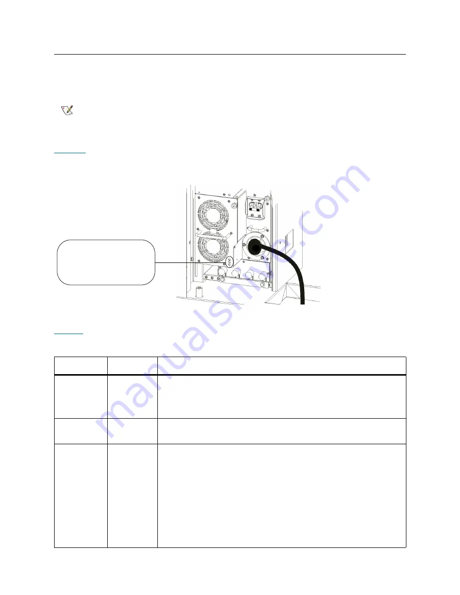
shows the locations and colors of the power supply LEDs.
Figure 50
Locations and Colors of Power Supply LEDs
describes how to interpret LED activity that you might see.
Note
The library can be physically configured to include up to eleven expansion
modules. The first seven expansion modules can contain power supplies if
drives are present.
Table 29
Explanations of Power Supply LED States
LED Color
Represents
Possible States and Explanations
Green
(top LED)
AC OK
• Solid on — power supply’s AC input is above minimum requirements
to operate
• Solid off — power supply’s AC input is below minimum requirements
to operate
Green
(middle LED)
DC OK
• Solid on — power supply’s output voltage is within specifications
• Solid off — power supply’s output voltage is outside of specifications
Blue (bottom
LED)
Fault
• Solid on — indicates any of the following conditions:
•Power supply output is outside of specifications
•Current limit has been exceeded
•Temperature limit has been exceeded
•Fan failed while AC input is present and above minimum operating
voltage
•AC input is below minimum operating voltage
•PDU is on, but the
Power
button on the library’s indicator panel is off
• Solid off — no faults are detected
power supply LEDs
- top (AC OK) = green
- middle (DC OK) = green
- bottom (FAULT) = blue
Summary of Contents for Scalar i6000
Page 20: ...8 About This Guide and Your Product...
Page 38: ...26 Installing a Stand Alone Control Module...
Page 104: ...92 Installing a Multi Module Library...
Page 156: ...144 Installing Cartridges...
Page 164: ...152 Setting up Your Library for Access...
Page 242: ...230 Configuring the Library...
Page 304: ...292 Adding Optional Hardware eight 2 5 mm screws...
Page 318: ...306 Adding Optional Hardware...
Page 336: ...324 Installation Testing and Verification Figure 35 Example Test Log Output...
Page 356: ...344 Testing and Calibrating the Digital Level...
Page 362: ...350 LBX Board and Terminator...
Page 380: ...368 Glossary...
Page 384: ...372 Index...