


Quantum Scalar i500: Ethernet Expansion Blade Installation
6-68141-01 Rev A
April 2014
Installing the Ethernet Expansion Blade
5
You must do this BEFORE placing the Ethernet Expansion blade into the
library.
6
Prepare the library for Ethernet Expansion blade installation. The Ethernet
Expansion blade must be installed in the lower left bay of an expansion
module.
• In some cases, installing the Ethernet Expansion Blade may require
removal or relocation of an FC I/O blade and its accompanying fan
blade.
• Remove the cover plate covering the two bottom left slots. To remove
the cover plate, unscrew the two captive thumbscrews securing the
cover plate and pull outward on the plate. Save the cover plate in case
you need to use it later.
7
Remove the new Ethernet Expansion blade from the protective anti-static
bag.
8
Press up and out to open the latch hooks on each side of the blade. Hold the
Ethernet Expansion blade upright with the latch hooks on the left side, and
the status LEDs at the bottom (see
9
Carefully align the Ethernet Expansion blade with the guide slots in the bay.
Caution:
Forcing the blade into the bay can cause the pins to bend.
10
Evenly apply pressure to both sides of the blade and slide it into the
expansion module until the latch hooks begin to move toward the middle of
the blade. Push the latch hooks toward the middle of the blade and into the
locked position. You will feel the blade pins connect with the expansion
module’s backplane as the blade locks into place.
The status LEDs on the Ethernet Expansion blade should be as follows: The
blue LED should blink once every 10 seconds, indicating the blade is
powered on. The green LED should blink once per second, indicating the
blade’s processor is working normally. The amber LED should be off. If the
LEDs are not blinking properly, reseat the blade.
Caution:
Be sure the cover plate is installed over the empty bay to the
right of the Ethernet Expansion blade. If the cover plate next to
an Ethernet Expansion blade is not installed, Ethernet
Expansion blade temperature errors will occur.
11
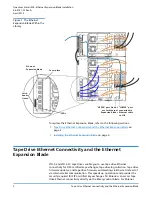
Cable the Ethernet Expansion blade (see
Cabling the Ethernet Expansion
12
Power on the library.
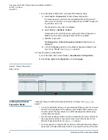
13
Verify that the Ethernet Expansion blade is in the “Ready” state using one of
the following methods:
• Check the LEDs on the Ethernet Expansion blade.
The green LED should blink once per second, the blue LED should blink
once every 10 seconds, and the amber LED should be off.


