background image

Warning

!

26

Warranty

3

WARRANTY VOUCHER


    Model

.........................

    Serial number

.........................

    Defect found

...........................................................................


Customer signature

      Date  _ _ / _ _ / _ _                                                    

.............................

 To return correctly filled in together with the purchase receipt

DEALER’S STAMP AND SIGN

Warranty


Dear customer,

  thank you for choosing our product, which has been designed and manufactured to the highest quality standards.

    • The product is covered by a warranty, for a period of 24 months, which is testified from a delivery document indi-

cating the date of purchase of the product and the dealer’s name. 

  • The customer is entitled to the rights provided for by Legislative Decree n° 24/2002

  • The warranty covers the replacement or the repair operation of all the parts found to have manufacturing 

defects.

  • The warranty does not cover:  

›  failures caused by carelessness or transport.

›  failures caused by installation not in accordance with the instructions 

›  failures caused by improper, incorrect or not in accordance with the instructions, use of the  device 

  • The manufacturer cannot be held responsible for accidental damages to persons, pets, or things,  as a conse-

quence of non-conformity with all the precautions furnished with the instructions manual.

›  In the event you require service, during the warranty period, you should fill in and show the present cer-

tificate, together with a valid receipt issued by the dealer, showing the date of purchase of the prod-
uct.

CAUTION


This  symbol  means  impor-

tant  instructions.  Failure  to  heed 
them can result in serious injury or 
death

U S E  T H E  C O R R E C T  A M P E R E  
R A T I N G  W H E N  R E P L A C I N G  
FUSES

   Failure to do so may result in fire or
   electric shock

H A L T  U S E  I F  A  P R O B L E M  
APPEARS

   Failure to do so may cause personal

D O   N O T   O P E R A T E   A N Y  

   injury or damage to the product.

FUNCTION  THAT  TAKES  YOUR 

DO NOT USE OLD BATTERIES

ATTENTION AWAY FROM SAFELY 

   When inserting batteries in the

DRIVING YOUR VEHICLE

   remote control, be sure to observe

Any  function  that  requires  your 

   proper polarity as instructed.

prolonged attention should only be

   Rupture or chemical leakage from

performed after coming to a

   the battery may cause malfunction

complete stop.

   ing, break or injury.

Always stop your vehicle in a safe
location before performing these
functions. Failure to do so may result
in an accident.

USE THIS PRODUCT FOR MOBILE 
12/24 Vcc APPLICATIONS AND 
NEGATIVE GROUND

 Any misuse that diverts from the 
 designed application may result in
 fire, electric shock or other injury.

DO NOT DISASSEMBLE OR ALTER 
THE UNIT

   Doing so may result in accidents or
   injuries.


Summary of Contents for QTM10

Page 1: ...QTM10 User manual Manufactured and distributed by Quantum s p a Via Piero e Alberto Pirelli 6 20126 MILANO www qtm it info qtm it...

Page 2: ...ly Use pag 10 Menu pag 12 Settings pag 13 Tv List pag 15 Diagnostics pag 16 Audio Video Switching pag 17 Installation pag 19 Installation and Connections pag 20 Technical features pag 24 Warning pag 2...

Page 3: ...nual In the event you require service during the warranty period you should fill in and show the present cer tificate together with a valid receipt issued by the dealer showing the date of purchase of...

Page 4: ...nsure vehicle safety fully check all electrical connections the driver s side screen must be con to prevent short circuits Also have nected to the front video output con your vehicle s voltage regulat...

Page 5: ...Diversity with Anti Doppler Enhancement DVB MPEG2 Transport and De Multiplexing ISO IEC 13818 1 MPEG 2 Transport Stream Compliance Nordig II and ETS 300 744 DVB T Full Compliance Full 47 860 MHz Frequ...

Page 6: ...1 CONNECTOR Connector for the remote control sensor 1 2 v TECHNICAL FEATURES Operation frequencies 174 230 band III 470 862 bands IV V Gain 14 2 dB Cable type coaxial 75 ohm Cable lenght 5 m Connector...

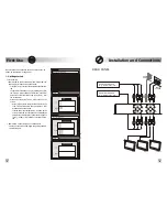
Page 7: ...xperi ment where to place the antennas whether on the higher or the lower part of the window The higher part usually guarantees more protection from noises caused by motorcycles and scooters Handle wi...

Page 8: ...nd the installation parameters of the receiver then press in sequence buttons to restart the tun ing on the front panel switched off check the connections and begin the getting started operations agai...

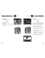
Page 9: ...IAGNOSTICS CREATE SORT DEL CHAN DEL LIST FAVOURITE TV TV LIST 1 Channel TV 2 Channel TV 3 Channel TV 4 Channel TV 5 Channel TV 6 Channel TV 7 Channel TV GREEN to change list 1 1 v Autotracking and Aut...

Page 10: ...ESSORY PARTS shock or injury due to electrical shorts Be sure to use only the specified acces sory parts Use of other than designed DO NOT SPLICE INTO ELECTRICAL accessory parts may damage this unit o...

Page 11: ...s info GREEN and select the desired language by using the up down 5 6 buttons channels marked with this symbol are temporarily not available network coverage 1 FAVOURITE TV 1 Channel TV 2 Channel TV 3...

Page 12: ...eiver displays the signal from A V IN1 input AV 1 Press A V again Frame 3 will be shown on the screen and after a few seconds the receiver displays the signal from A V IN2 input AV 2 Press A V again F...

Page 13: ...Settings Menu press MENU to view the main menu on the screen select SETTINGS by using the right and left 3 4 buttons press OK to enter this sub menu and then press it again till you get the required...

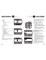
Page 14: ...s OK to confirm select CREATE and press OK to confirm browse the list sequentially by using the up and down buttons 5 6 or in groups of six channels by using right and left buttons 3 4 and select the...

Reviews: