background image

Chapter 1  Introduction
Operator Accessible Components

6

Quantum|ATL 7100 Series Library Operator’s Guide

Operator Accessible Components

1

Control Panel

1

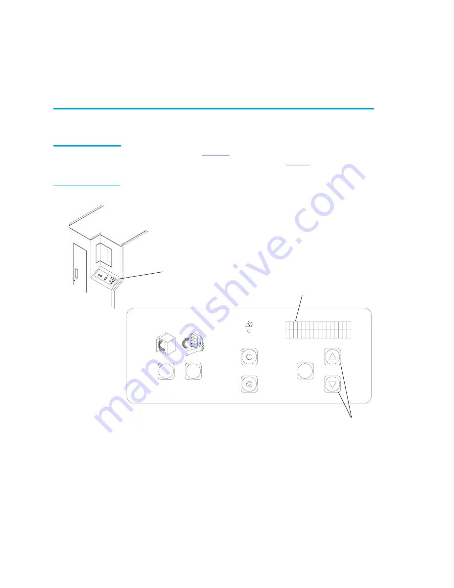
The control panel (

figure 4

) is located on the right side at the front 

of the library. Its features are described in 

table 1

.

Figure 4  Control 
Panel

STOP

OPEN

CLOSE

STANDBY

FAULT

SELECT

Control panel

Status display area
(16 characters/2 lines)

Scrolling buttons
(Up {

} and down {

})

Summary of Contents for ATL 7100

Page 1: ...Quantum ATL 7100 Series Library Operator s Guide 6241102 02 Ver 2 Rel 2 ...

Page 2: ...o time without notice Quantum ATL is the generally known alternative designation of ATL Products Inc COPYRIGHT STATEMENT Copyright 2001 by ATL Products Inc All rights reserved Your right to copy this manual is limited by copyright law Making copies or adaptations without prior written authorization of ATL Products Inc is prohibited by law and constitutes a punishable violation of the law TRADEMARK...

Page 3: ...brary Numbering Conventions 3 Operator Accessible Components 6 Control Panel 6 Load Port 8 Front Door 10 Storage Array Door 11 Drive Access Door 12 Rear Panel 13 Chapter 2 Operating the Library 15 Operating Procedures 15 Applying Power to the Library 15 Placing the Library Online 16 Taking the Library Offline 16 ...

Page 4: ...ing Disabling the Auto Clean Option 34 Enabling Disabling the Retries Option 35 Enabling Disabling the Auto Load Option 36 Setting the Status Display Area Language 37 Adjusting the Status Display Area Contrast 38 Cleaning a Drive 40 Displaying the Library s Actuator Status 41 Performing an Inventory 43 Enabling Disabling 4 52 Identity Mode 44 Chapter 3 Operator Troubleshooting 47 Status Messages 4...

Page 5: ...Contents Quantum ATL 7100 Series Library Operator s Guide v Index 61 ...

Page 6: ...Contents vi Quantum ATL 7100 Series Library Operator s Guide ...

Page 7: ...igure 5 Load Port 9 Figure 6 Front Door 10 Figure 7 Storage Array Door 11 Figure 8 Drive Access Door 12 Figure 9 Rear Panel 13 Figure 10 Bar Code Label on a Tape Cartridge 17 Figure 11 Inserting and Removing Tapes 18 Figure 12 Tape Cartridge Orientation 21 Figure 13 Turning the Interior Light On Off 23 Figure 14 Menu Structure 25 Figure 15 Menu Navigation Example 26 ...

Page 8: ...Figures viii Quantum ATL 7100 Series Library Operator s Guide ...

Page 9: ...ary Operator s Guide ix Tables Table 1 Controls on the Control Panel 7 Table 2 Default Tape Drive SCSI Address 30 Table 3 Tape Drive Locations 32 Table 4 Tape Drive Locations 41 Table 5 Status Messages 48 Table 6 Other Problems 49 ...

Page 10: ...Tables x Quantum ATL 7100 Series Library Operator s Guide ...

Page 11: ...e of storing a maximum of 96 tape cartridges in a Fixed Storage Array FSA An operator accessible load port at the front of the library can hold an additional four tape cartridges for a maximum total of 100 Audience This document was written for operators of the library Purpose This document provides information about the library including Installing the library Basic library operations Operator co...

Page 12: ...are succeeded by b h All hexadecimal numbers are succeeded by h Error or attention conditions are represented in parenthesis that translate as follows SK S ASC AA ASCQ QQ where S hexadecimal sense key value AA hexadecimal additional sense code QQ hexadecimal additional sense code qualifier Caution Cautions indicate potential hazards to equipment and are included to prevent damage to equipment Note...

Page 13: ...ument Title Document Description 6241101 Quantum ATL 7100 Series Library Facilities Planning and Installation Guide Describes facility preparation and provides the procedures for first time installation of the library 6241104 Quantum ATL 7100 Series Library DiagnosticSoftware User s Manual Provides procedures for installing and using the Quantum ATL 7100 Series Diagnostic Software 6241105 Quantum ...

Page 14: ...9 7100 949 856 7800 800 284 5101 Technical Publications 0 To comment on existing documentation send e mail to atl docs atlp com Visit the Quantum ATL home page at 0 http www atlp com Customer Support 0 The Quantum ATL Customer Support Department provides a 24 hour help desk that can be reached at North South America 949 725 2100 or 800 284 5101 Asia Pacific Rim International Code 61 7 3862 4834 Eu...

Page 15: ... South America 949 725 2176 Asia Pacific Rim International Code 61 7 3862 4677 Europe Middle East Africa International Code 44 0 1256 848777 Send e mail for the Customer Support Department to North South America helpdesk atlp com Asia Pacific Rim ATL helpdesk apac atlp com Europe Middle East Africa ukhelpdesk atlp com ...

Page 16: ...Preface xiv Quantum ATL 7100 Series Library Operator s Guide ...

Page 17: ...the operator accessible components Overview 1 The library is an automated tape storage and retrieval system see figure 1 It accomodates up to seven tape drives and is capable of storing a maximum of 96 tape cartridges in a Fixed Storage Array FSA An operator accessible load port at the front of the library can hold an additional four tape cartridges for a maximum total of 100 ...

Page 18: ...rary Operator s Guide Figure 1 Library Load port open 4 additional cartridges Control Panel Fixed Storage Array FSA 96 cartridge bins Gripping mechanism gripper Horizontal carriage Vertical carriage Front Left side cosmetic panel removed Tape drives 7 Door handle ...

Page 19: ...ad port To transfer a cartridge a gripping mechanism aligns itself with the designated tape cartridge and picks it from the FSA component It then moves and aligns itself with the designated location within the FSA and places the tape cartridge Library Numbering Conventions 1 All FSA components storage bins load port bins and tape drives are numered Figure 2 shows the numbering convention for the 1...

Page 20: ... Bin 30 Bin 31 Bin 32 Bin 33 Bin 53 Bin 54 Bin 55 Bin 56 Bin 57 Bin 77 Bin 78 Bin 79 Bin 80 Bin 81 Bin 10 Bin 11 Bin 12 Bin 13 Bin 14 Bin 34 Bin 35 Bin 36 Bin 37 Bin 38 Bin 58 Bin 59 Bin 60 Bin 61 Bin 62 Bin 82 Bin 83 Bin 84 Bin 85 Bin 86 Bin 15 Bin 16 Bin 17 Bin 18 Bin 19 Bin 39 Bin 40 Bin 41 Bin 42 Bin 43 Bin 63 Bin 64 Bin 65 Bin 66 Bin 67 Bin 87 Bin 88 Bin 89 Bin 90 Bin 91 Bin 20 Bin 21 Bin 22 ...

Page 21: ... 33 Bin 48 Bin 49 Bin 2 Bin 3 Bin 4 Bin 5 Bin 6 Bin 18 Bin 19 Bin 20 Bin 21 Bin 22 Bin 34 Bin 35 Bin 36 Bin 37 Bin 38 Bin 50 Bin 51 Bin 52 Bin 53 Bin 54 Bin 7 Bin 8 Bin 9 Bin 10 Bin 11 Bin 23 Bin 24 Bin 25 Bin 26 Bin 27 Bin 39 Bin 40 Bin 41 Bin 42 Bin 43 Bin 55 Bin 56 Bin 57 Bin 58 Bin 59 Bin 12 Bin 13 Bin 14 Bin 15 Bin 28 Bin 29 Bin 30 Bin 31 Bin 44 Bin 45 Bin 46 Bin 47 Bin 60 Bin 61 Bin 62 Bin 6...

Page 22: ...tor Accessible Components 1 Control Panel 1 The control panel figure 4 is located on the right side at the front of the library Its features are described in table 1 Figure 4 Control Panel STOP OPEN CLOSE STANDBY FAULT SELECT Control panel Status display area 16 characters 2 lines Scrolling buttons Up and down ...

Page 23: ...s the library between online mode and standby mode On line mode normal operation the red indicator is Off Standby mode host communications are disabled the control panel menu mode is available the diagnostic port on the rear panel DIAG is active and the red indicator is On If chosen during a transfer operation the library completes the operation before standby mode is active the red indicator blin...

Page 24: ...ape cartridges in the load port bins Looking through the view port the operator will be able to decide if an unload operation is necessary Pressing the OPEN button automatically opens the door allowing the operator to remove the tape cartridge s FAULT Indicator The FAULT indicator illuminates when the library has an error condition The SDA displays the name of the error condition For a listing and...

Page 25: ...Chapter 1 Introduction Operator Accessible Components Quantum ATL 7100 Series Library Operator s Guide 9 Figure 5 Load Port Load port closed Cartridge View port Closes to left Load port open ...

Page 26: ...ically done by field service engineers during maintenance procedures For safety purposes an interlock switch removes power from the robotics equipment when the door is opened Always press the STANDBY button to open any library door Do not open until the STANDBY indicator blinks then becomes solid System Off line is then displayed on the SDA Figure 6 Front Door open to right Handle Front door open ...

Page 27: ...ridges see figure 7 For safety purposes an interlock switch removes power from the robotics equipment when the door is opened Always press the STANDBY button to open any library door The FAULT indicator flashes until the current command is completed Wait until the STANDBY indicator is on solid and System Off line is displayed before opening the door Figure 7 Storage Array Door Storage array door ...

Page 28: ...d is not normally used by operators For safety purposes an interlock switch removes power from the robotics equipment when the door is opened Always press the STANDBY button to open any library door The FAULT indicator flashes until the current command is completed Wait until the STANDBY indicator is on solid and System Off line is displayed before opening the door Figure 8 Drive Access Door Drive...

Page 29: ...eceptacle and the communication ports for the host tape drives and diagnostic PC see figure 9 The operator s only responsibility concerning the rear panel is to verify the cables are properly connected and to turn library power on or off with the AC power switch Figure 9 Rear Panel AC power receptacle and power switch DIAG RS 232 diagnostic port SCSI ports port 8 at top port 1 at bottom ...

Page 30: ...Chapter 1 Introduction Operator Accessible Components 14 Quantum ATL 7100 Series Library Operator s Guide ...

Page 31: ...ting procedures Adding or removing tape cartridges Using the control panel Operating Procedures 2 Applying Power to the Library 2 To apply power to the library 1 Verify the following Front door and load port are closed All outer panels are attached All back panel connections are secured 2 At the back panel set the AC power switch to the I on position ...

Page 32: ...em On line press the control panel STANDBY button 2 The library robotics will stop after completing the current command s Verify that System Off line is displayed in the SDA Removing Power from the Library 2 To remove power from the library 1 Press the control panel STANDBY button The library robotics will stop after completing the current command s Verify that System Off line is displayed in the ...

Page 33: ...o the front face see figure 10 Figure 10 Bar Code Label on a Tape Cartridge Adding Tape Cartridges Through the Load Port 2 To add a tape cartridge through the load port 1 Verify that each cartridge has a bar code label Note Enable the auto load option before performing this task see Enabling Disabling the Auto Load Option on page 36 Caution DO NOT USE CompacTape I CompacTape II or CompacTape IIIXT...

Page 34: ...ess the load port CLOSE button 5 When the CLOSE indicator is steadily lit push the load port door closed The library will lock the door Figure 11 Inserting and Removing Tapes Caution Mechanical hazards could be exposed when the load port is partially open or closed Do not attempt to insert hands or fingers into the load port opening at any time Caution The load port door is locked in the open posi...

Page 35: ... steadily lit push the load port door closed The library locks the door Bulk Loading or Unloading of Cartridges 2 It is recommended to add or remove tape cartridges from the library using the load port However there may be situations such as initial loading of the library when you need to load or unload a Note Use the view port to determine if the load port contains tape cartridges to be removed W...

Page 36: ... If the library is powered on press the control panel STANDBY button The library robotics will stop after completing the current command s Verify that System Off line is displayed in the SDA 3 Open the storage array door 4 Unload and or load tape cartridges in the bins When loading a cartridge insert the cartridge in the proper orientation see figure 10 bar code label facing out and on the left si...

Page 37: ...Chapter 2 Operating the Library Operating Procedures Quantum ATL 7100 Series Library Operator s Guide 21 Figure 12 Tape Cartridge Orientation ...

Page 38: ...em Off line is displayed in the SDA 2 Open the front door by pulling the door towards you The door opens to your right 3 Reach through the front door and set the light switch on the far side of the light to the desired position see figure 13 4 Close and latch the library front door 5 Press the control panel STANDBY button and verify that System On line is displayed in the SDA Note The load port bi...

Page 39: ... Turning the Interior Light On Off Using the Control Panel Menus 2 Entering Menu Mode 2 To enter menu mode 1 Press the control panel STANDBY button and verify the SDA displays System Off line 2 Press the SELECT button to enter menu mode Verify the following is displayed in the SDA Power Interior light opens to right switch ...

Page 40: ...and down arrow buttons line 2 scrolls through the options available for the current menu When you press the SELECT button the submenu or function displayed on line 2 is selected or executed There is an Exit option at the end of each menu submenu and option list When you select Exit you are returned to the previous menu The overall structure the menus is shown in figure 14 Figure 15 is an example o...

Page 41: ...figuration Drive Control Calibration System Test Robot Control Diagnostics Main Menu Exit Menu Report Results Random Shuffle Pick Each Bin Exit Menu Inquiry SCSI Address Power Up State Num of Drives Auto Clean Retries Auto Load Language Set View Auto Inventory No Barcode Scan Emulate Exabyte 4 52 Identity Temperature Det Unload Clean Exit Menu Random No Scan Pick All Empty Load Port Pick Bin Pick ...

Page 42: ...nu Ø Bypass the SCSI Address submenu Ø Bypass the Power Up State submenu Ø Bypass the Num of Drives submenu SELECT Choose the Auto Clean submenu SELECT Select the Enabled Option The SDA displays the status SUCCESS when the function is finished Press the or button and the SELECT button simultaneously to exit the menu mode or use them separately to navigate to the Exit or another function Status Dis...

Page 43: ...nsor status Status Sensor Command a robotic actuator to move Move Actuator Perform a library inventory Inventory Exercise the library robotic actuators Exercise All This section only describes how to use the Diagnostics menu option for performing a self test to verify proper configuration and operation of the library For a description of other Diagnostic menu options refer to the Quantum ATL 7100 ...

Page 44: ...yed in the SDA 3 Press the button until Diagnostics is displayed in the SDA 4 Press the SELECT button to select the Diagnostics menu Verify the following is displayed in the SDA 5 Press the button until Selftest All is displayed in the SDA 6 Press the SELECT button The following is displayed in the SDA 7 The self test should take several seconds to complete If the self test completes successfully ...

Page 45: ...he following is displayed in the SDA 4 Press the SELECT button to choose the SCSI Address submenu and verify the following is displayed in the SDA 5 Press the SELECT button to choose the Robotics submenu and verify the following is displayed in the SDA 6 Use the and buttons to navigate to the SCSI ID number for the library 7 With the proper SCSI ID number displayed on line 2 press the SELECT butto...

Page 46: ...efault Tape Drive SCSI Address To change the SCSI addresses of the drives in the library 1 Enter the menu mode Note After changing the SCSI address of the library one of two things must happen to set the new SCSI ID the host controller must issue a SCSI Bus Reset or the library must be powered off and on again SCSI Address Drive Number Physical Location 1 0 top drive 2 1 second drive 3 2 third dri...

Page 47: ...nquiry menu and verify the following is displayed in the SDA 4 Press the SELECT button again to choose SCSI Address and verify the following is displayed in the SDA 5 Use the button to bypass the Robotics submenu and verify the following is displayed in the SDA 6 Use the and buttons to select the proper drive number to set or change see table 3 Menu Configuration Inquiry Menu Configuration SCSI Ad...

Page 48: ...it the menu mode 11 After changing the SCSI address of the drives do one of the following to set the new SCSI ID Run the Reset Drives command from the Diagnostic Software Package Issue a SCSI Bus Reset from the host controller Power the library off and on again Tape Drive Number Physical Location Drive 0 top drive Drive 1 second drive Drive 2 third drive Drive 3 fourth drive Drive 4 fifth drive Dr...

Page 49: ... the SDA 3 Use the button to bypass the Inquiry menu and verify the following is displayed in the SDA 4 Press the SELECT button to choose the Power Up State menu and verify the following is displayed in the SDA 5 Use the button to bypass the System On line option and verify the following is displayed in the SDA 6 With the desired option displayed on line 2 press the SELECT button 7 Exit the menu m...

Page 50: ...ve and determining when a cleaning tape cartridge has been used up With auto clean enabled the library monitors each drive s status to determine when a drive requires cleaning and initiates action when that determination is made The library selects an available cleaning tape cartridge handles media movement of the cleaning tape cartridge to and from the drive and supervises the cleaning operation ...

Page 51: ...splayed on line 2 press the SELECT button 6 Exit the menu mode Enabling Disabling theRetries Option2 When the retries option is enabled the library attempts to recover from internal anomalies to complete a host command 1 Enter the menu mode 2 Press the SELECT button to choose the Configuration menu 3 Verify the following is displayed in the SDA 4 Use the button to bypass the Inquiry SCSI Address P...

Page 52: ...ed storage array without any intervention from the host controller When this option is enabled the library automatically finds bins in the FSA for cartridges that are placed in the load port If no bin locations are available in the FSA the cartridges are left in the load port bin and an error message is displayed on the control panel SDA The default for the auto load option is disabled To change t...

Page 53: ...ed in the SDA 6 Use the button to bypass the Enabled option and verify the following is displayed in the SDA 7 With the desired option displayed on line 2 press the SELECT button 8 Exit the menu mode Setting the Status Display Area Language 2 The language of text displayed in the status display area SDA can be set to any of the following English default Francais Deutsch Espanol Italiano Menu Confi...

Page 54: ...s displayed in the SDA 5 With Language displayed on line 2 of the SDA press the SELECT button and verify the following is displayed in the SDA 6 Use the and buttons to navigate to the desired language 7 With the desired language displayed on line 2 press the SELECT button 8 Exit the menu mode Adjusting the Status Display Area Contrast 2 To adjust the status display area contrast 1 Enter the menu m...

Page 55: ...uto Load and Language sub menus and verify the following is displayed in the SDA 5 With Set View displayed on line 2 of the SDA press the SELECT button and verify the following is displayed in the SDA 6 Use the and buttons to navigate to the desired contrast 7 With the desired contrast displayed on line 2 press the SELECT button 8 Exit the menu mode Menu Configurati Set View Menu Set View Contrast...

Page 56: ...s displayed in the SDA 3 Press the SELECT button to choose the Drive Control menu 4 Verify the following is displayed in the SDA 5 Use the button to bypass the Unload submenu Verify the following is displayed in the SDA 6 Press the SELECT button to choose the Clean sub menu and verify the following is displayed in the SDA 7 Use the and buttons to select the proper drive number see table 3 8 With t...

Page 57: ...ntal vertical extension gripper in the library You can use this option to test for proper operation and tracking of each actuator 1 Enter the menu mode 2 Use the button to bypass the Configuration Drive Control Calibration System Test and Robot Control menus and verify the following is displayed in the SDA Menu Clean Drive n Tape Drive Number Physical Location Drive 0 top drive Drive 1 second driv...

Page 58: ...t to display Status Actuator or Status Sensor 6 With the selection displayed on line 2 press the SELECT button 7 Use the and buttons to scroll through the SDA line 2 displays to review the information returned The following is an example for a status actuator 1 51 horizontal position 11 8 vertical position 3 25 extension position c gripper state closed open unknown 8 When you have finished viewing...

Page 59: ...y 1 Enter the menu mode Verify the following is displayed in the SDA 2 Use the button until Diagnostics is displayed in the SDA 3 Press the SELECT button to select the Diagnostics menu Verify the following is displayed in the SDA 4 Press the button until the Inventory option on the Diagnostic menu is displayed Note Inventory information is maintained in system RAM and is not retained if the system...

Page 60: ...ry without changing the host software Note With a full library the inventory takes less than three minutes if all cartridges are properly bar code labeled The actual inventory time takes longer if the library is not completely full or if any of the cartridges are not properly labeled When the library is full of unlabeled cartridges the inventory may take over 27 minutes Menu Inventory Success Note...

Page 61: ...owing is displayed in the SDA 4 Press the button until 4 52 Identity is displayed in the SDA 5 Press the SELECT button to select 4 52 Identity and verify the following is displayed in the SDA 6 Use the and buttons to display the desired option Enabled Disabled or Exit Menu 7 With the desired setting displayed on line 2 press the SELECT button 8 Exit the menu mode Menu Configurati Inquiry Menu Conf...

Page 62: ...Chapter 2 Operating the Library Using the Control Panel Menus 46 Quantum ATL 7100 Series Library Operator s Guide ...

Page 63: ...tion necessary if any to rectify specific problems Status Messages 3 Table 5 lists of all status messages displayed in the SDA The status message column shows the two lines of the SDA If there is only one line of text in the message it is displayed on line 1 The description action column provides a brief explanation of the message and where necessary steps that you can take to resolve any problem ...

Page 64: ...ine but must complete a command that is currently executing When finished System Off line is displayed in the SDA System Power Up This is the first message displayed in the SDA when the library power is cycled from off to on Initializing Wait for On line This is the second message displayed in the SDA after System Power Up when the library power is cycled from off to on When the library successful...

Page 65: ...Administrator Note For a problem not listed in table 6 notify your FSE Problem Resolution A tape drive is not ejecting the cartridges properly Use the procedure described in the tape drive documentation to remove the cartridge If the problem persists notify your FSE One or more cables are disconnected from the ports on the rear panel Perform the procedure described in Removing Power from the Libra...

Page 66: ...Chapter 3 Operator Troubleshooting Other Problems 50 Quantum ATL 7100 Series Library Operator s Guide ...

Page 67: ...s operated in a commercial environment This equipment generates uses and can radiate radio frequency energy and if not installed and used in accordance with the instruction manual may cause harmful interference to radio communications Any changes or modifications made to this equipment may void the user s authority to operate this equipment Operation of this equipment in a residential area may cau...

Page 68: ...ference Causing Equipment Regulations Cet appareil numérique de la classe A respecte toutes les exigences du Reglément sur le matériel brouilleur du Canada CISPR 22 WARNING 0 This is a Class A product In a domestic environment this product may cause radio interference in which case the user may be required to take adequate measures ACHTUNG 0 Dieses ist ein Gerät der Funkstörgrenzwertklasse A In Wo...

Page 69: ... AWG 1 5 mm2 or 18 AWG 1 0 mm2 wires Length Maximum 15 feet 4 5m Rating Minimum 10 A 125 V ATTENTION 0 LIRE LA REMARQUE DANS LE MODE D EMPLOI REMARQUE 0 CETTE REMARQUE NE CONCERNE QUE LES ÉTATS UNIS ET LE CANADA En cas d envoi aux États Unis utiliser le cordon d alimentation CERTIFIÉ UL et convenant pour 100 120 V En cas d envoi au Canada utiliser le cordon d alimentation CERTIFIÉ CSA et convenant...

Page 70: ...t Laserstrahlen aus VERMEIDEN SIE jeden Blickkontakt und direkten kvrperlichen Kontakt mit diesen Strahlen VORSICHT Ein nicht ordnungsgemd_er siehe hier enthaltene Anweisungen Einsatz bzw Dnderungen der Betriebsleistung kvnnen einen gesundheitsgefdhrdenden Kontakt zur Folge haben Appareil à Laser de Classe 1 0 ATTENTION Ce produit émet de la classe laser II Rayonnement laser NE PAS fixer des yeux ...

Page 71: ... rischi all incolumit delle persone Battery Statement 0 CAUTION 0 This product contains a Lithium battery The Dallas Semiconductor DS12B887 on the motherboard contains a Lithium battery Lithium may be considered a hazardous material Dispose of this battery in accordance with local state and federal laws LET OP 0 Dit product bevat een lithiumbatterij De DS12B887 chip van Dallas Semiconductor op het...

Page 72: ...d Regelungen betreffend Sammel und Rückgabestellen beachtet werden Attenzione 0 Questo prodotto contiene una batteria al litio Il modulo Dallas Semiconductor DS12B887 contiene una batteria al litio sulla scheda madre Il litio può essere considerato un materiale pericoloso Utilizzare questo tipo di batterie in accordo con le normative vigenti PRECAUCIÓN 0 Este producto contiene una batería de litio...

Page 73: ...trol bar code label The identification label on tape cartridges bar code scanner A device that is mounted on the extension axis that reads the cartridge bar code labels C calibration The software measurements and configuration required for successful operation of the library control panel The panel on the front of the library that contains the Status Display Area as well as indicators and control ...

Page 74: ...ore up to 96 cartridges in the library FSE Field Service Engineer G gripper assembly The assembly that mounts on the extension axis and grips cartridges referred to as the gripper H horizontal belt The drive belt connecting the horizontal motor to the horizontal axis assembly host or host computer The computer that issues SCSI commands to control the library robotics L LCD Liquid Crystal Display l...

Page 75: ... storing and handling cartridges R RAM Random Access Memory rear panel The rear cosmetic panel of the library that contains the AC power switch AC power receptacle and connectors for attaching external cabling to the library RS 232 A serial communications cabling and protocol standard for 9 pin connectors S SCSI Small Computer System Interface a communications standard for attaching peripheral equ...

Page 76: ...rtical belt The drive belt connecting the vertical motor to the vertical axis assembly vertical carriage assembly The crossbar and linear bearings mounted on the vertical rails and all components mounted on the crossbar Z ZIF connector Zero Insertion Force connector ...

Page 77: ...34 Auto load feature menu 36 C Cleaning a drive menu 40 Contrast adjusting 38 Control panel 6 D Diagnostics 28 Digital Linear Tapes 1 Display contrast settings 39 F Fixed Storage Array ix 1 bin numbering 3 Front door 10 I Inventory elapsed time 44 menu 43 L Language languages supported 38 status display area language menu 37 Library placing online 16 ...

Page 78: ...s 3 O Operator accessible components control panel 6 front door 10 load port 8 rear panel 13 Operator troubleshooting other problems 49 status messages 47 P Power applying 15 removing 16 Power up state menu 33 R Rear panel 13 Retry option menu 35 S SCSI address menu setting changing drive 30 setting changing library 29 SCSI II specification xi SCSI interface 3 Self test 28 T Tape cartridge removin...

Reviews: