background image

Bit Error Rate Tester | BERT 1005 

Quantifi Photonics Ltd. 

Version 

2.04


Copyright © 2022 Quantifi Photonics Ltd. All rights reserved.  

No part of this publication may be reproduced, stored in a retrieval system, or transmitted in any form, 
be it electronically, mechanically, or by any other means such as photocopying, recording or otherwise, 

without the prior written permission of Quantifi Photonics Ltd. (Quantifi Photonics). 

Information provided by Quantifi Photonics is believed to be accurate and reliable. 
However, no responsibility is assumed by Quantifi Photonics for its use nor for any infringements of 

patents or other rights of third parties that may result from its use. No license is granted by implication 
or otherwise under any patent rights of Quantifi Photonics. 

The information contained in this publication is subject to change without notice. 

Trademarks


Quantifi Photonics

’ trade

marks have been identified as such. However, the presence or absence of such 

identification does not affect the legal status of any trademark. 

LabVIEW™, MATLAB® and Python® are trademarks of National Instruments, The MathWorks Inc., and the 

Python Software Foundation, respectively. Neither Quantifi Photonics nor any software programs or 

other goods or services offered by Quantifi Photonics are affiliated with, endorsed by, or sponsored by 
National Instruments, The MathWorks Inc., and the Python Software Foundation. 

Units of Measurement 

Units of measurement in this publication conform to SI standards and practices. 

EU Authorized Representative 

Certification Company 

Veluwezoom 42 
1327 AH ALMERE 
The Netherlands 

+31 (0)36 202 40 37 

[email protected]


Version: 2.04


Summary of Contents for BERT 1005 Series

Page 1: ......

Page 2: ...er any patent rights of Quantifi Photonics The information contained in this publication is subject to change without notice Trademarks Quantifi Photonics trademarks have been identified as such However the presence or absence of such identification does not affect the legal status of any trademark LabVIEW MATLAB and Python are trademarks of National Instruments The MathWorks Inc and the Python So...

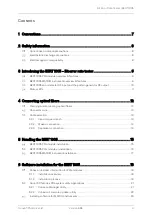
Page 3: ... optical fibers 12 Cleaning and connecting optical fibers 12 Connector care 13 Cable selection 13 4 3 1 Use a torque wrench 13 4 3 2 Make a connection 14 4 3 3 Separate a connection 14 5 Handling the BERT 1005 15 BERT 1005 PXIe module installation 15 BERT 1005 PXIe module uninstallation 16 BERT 1005 MATRIQ instrument installation 17 6 Software installation for the BERT 1005 18 Cohesion Installer i...

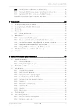
Page 4: ...or MATRIQ instruments 34 7 5 4 Setting the USB IP address for MATRIQ instruments 35 7 5 5 Setting the Ethernet IP address for MATRIQ instruments 35 SCPI Command Console available on PXIe modules 36 Info panel 39 8 BERT 1005 control with CohesionUI 40 Module configuration 41 8 1 1 Set up the data rate 41 8 1 2 Configure the trigger out signal 42 Check channels status 43 Error detection 44 8 3 1 Err...

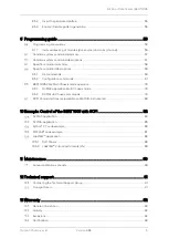
Page 5: ...commands 61 BERT 1005 PXIe Multi Chassis mode operation 78 9 6 1 NI MAX application Multi Chassis mode 78 9 6 2 SCPI Multi Chassis commands 79 SCPI Command Console available on MATRIQ instruments 80 10 Example Control of the BERT 1005 with SCPI 82 NI MAX application 84 NI VISA application 85 Python 2 7 code example 86 MATLAB code example 87 LabVIEW application 88 10 5 1 Soft Panels 88 10 5 2 LabVI...

Page 6: ...Bit Error Rate Tester BERT 1005 Quantifi Photonics Ltd Version 2 04 6 Service and repairs 93 ...

Page 7: ...met and understood Indicates a potentially hazardous situation which if not avoided may result in minor or moderate injury Do not proceed unless the required conditions are met and understood Indicates a potentially hazardous situation which if not avoided may result in component damage Do not proceed unless the required conditions are met and understood Refers to information about this product th...

Page 8: ... precautions The BERT 1005 product is sensitive to electrostatic discharge ESD Store the unused product in the original protective electrostatic packaging that the product was shipped in Ensure that a wrist strap and grounding table mat is used when unpacking or handling the BERT 1005 product Proper grounding and ESD management practices should always be followed to ensure that no ESD damage is ca...

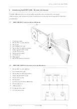
Page 9: ...Q instrument overview features 1 Status LEDs for error detector 2 Error detector RF input 3 Status LEDs for pattern generator 4 Pattern generator RF output 5 Divided clock output 6 Ethernet port 7 Ventilation fan DO NOT OBSTRUCT 8 Power supply port 9 USB type B port 10 IP address LCD screen 11 On Off push button 1 Fastening screws 2 Status LEDs for error detector 3 RF harness 4 Error detector RF i...

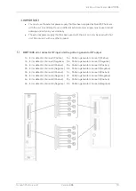
Page 10: ...e pattern generator RF output 1a Error detector channel 1 Positive 5a Pattern generator channel 1 Positive 1b Error detector channel 1 Negative 5b Pattern generator channel 1 Negative 2a Error detector channel 2 Positive 6a Pattern generator channel 2 Positive 2b Error detector channel 2 Negative 6b Pattern generator channel 2 Negative 3a Error detector channel 3 Positive 7a Pattern generator chan...

Page 11: ...fterwards the color changes to orange to show the initialization state of the system and then the LEDs are turned off For each channel of the pulse pattern generator PPG Green Pattern generation is running Off The module is powered off or no pattern generation is running For each channel of the error detector ED Green Error detection is running Orange Eye scan is running Off The module is powered ...

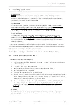
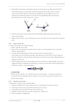
Page 12: ...l result in permanent damage to the connectors and degradation of future measurements Quantifi Photonics uses high quality connectors in compliance with EIA 455 21A standards Cleaning and connecting optical fibers To connect the fiber optic cable to the port 1 Inspect the fiber using a fiber inspection microscope If the fiber is clean proceed to connect it to the desired port 2 If the fiber is dir...

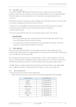
Page 13: ...rformance terminate the RF ports of all unused channels with 50 ohm terminators Cable selection When measuring differential signals or using the pattern generator to drive a differential circuit consider matching the phase of the cables being used The cables used to attach the DUT must have the same time difference and the same length For slow signals with large bit periods a cable mismatch such a...

Page 14: ...coaxial cables briefly short the centre conductor to the outer ground Long lengths of coaxial cable that have been disconnected at both ends can contain significant electrical charges at voltage potentials high enough to cause conducted static charge damage to high speed instruments 4 Carefully align the center axis of both devices Push the connectors straight together so they can engage smoothly ...

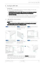
Page 15: ...uct is sensitive to ESD Ensure you are wearing a grounded wrist strap at all times when handling the BERT product to prevent damage from electrostatic discharge Take care not to handle the optical connectors on the BERT as once they are exposed to skin contact this may leave corrosive residue which can damage the connector DO NOT attempt to remove or adjust any component of the PXIe chassis while ...

Page 16: ...ERT 1005 PXIe module uninstallation STEP 1 Power OFF the chassis STEP 2 Unsecure the fastening screws and fastening clip STEP 3 Pull out the module USE THE FASTENING CLIP TO PULL DO NOT PULL ON THE CONNECTORS STEP 4 Store module in antistatic bag STEP 5 Power ON the chassis ...

Page 17: ... to use a different external power supply may cause product damage and will void your warranty The external power supply that has been used with the unit can only be used with that unit Do not use it with any other product STEP 1 Insert power cord STEP 2 Power ON the instrument STEP 3 via USB Connect USB cable STEP 3 via Ethernet Connect Ethernet cable STEP 4 IP address will appear on the LCD scre...

Page 18: ...e that contains all the required drivers and software to support and control Quantifi Photonics modules on the PXIe Platform 6 1 1 Installation overview For the PXIe Controller to communicate with the BERT 1005 module installed in the chassis software and driver installations are necessary This software is contained in the Cohesion Installer single installer package CohesionDriver Drivers for Quan...

Page 19: ...t installation type CohesionUI with Apache 4 Installation will continue with the Chassis Mode selection The default setting is Single Chassis Mode If unsure proceed with the default mode setting To operate in Multiple Chassis Mode additional hardware modules are required The Chassis Mode can be changed at any time so it is recommended to select Single Mode until all other configuration requirement...

Page 20: ... Finish to complete the installation process 6 Windows Security Alert may prompt the user for network access It is recommended that both options be ticked to allow any network configuration 7 After rebooting the system on startup a User Account Control prompt will be displayed to run the Cohesion Firmware Updater Utility Click Yes and proceed with the application ...

Page 21: ...are Services will start automatically on startup of the Windows OS and need to be running to facilitate proper communication with the Quantifi Photonics PXIe modules If there is an issue in detecting or communicating with the modules run the Cohesion Manager to check the status of the software services Required CohesionDriver The CohesionDriver service which directly manages the installed Quantifi...

Page 22: ...tion for more 6 2 1 information Whenever a new version of the CohesionInstaller is installed on the system the Cohesion Firmware Updater utility will automatically launch after the system is rebooted It will show the user the firmware status of all installed Quantifi Photonics modules and allow the user to update the firmware to a new version if applicable If a module s firmware is out of date it ...

Page 23: ...ckage is included on the USB media device that we provide with your instrument or you can download it from quantifiphotonics com go to Resources Drivers software and manuals MATRIQ Series If another MATRIQ instrument is already connected to the client computer over USB consult the Network and Update settings 7 5 4 section below on configuring the Ethernet USB IP address for multi instrument contro...

Page 24: ...ator from the Start menu From Cohesion Operator you can 1 Select a Quantifi Photonics instrument that is available on your network 2 Validate the IP address of the instrument and retrieve instrument information refer 6 3 2 3 Communicate with the instrument through the SCPI Command Console refer 9 7 4 Access the instrument through CohesionUI a web based graphical user interface refer 7 2 5 Upgrade ...

Page 25: ...oduct information You can check the details of a MATRIQ instrument for example by doing one of the following In the Cohesion Operator 1 Select the instrument 2 Click Connect 3 Current instrument information will be displayed In CohesionUI 1 Select INFO on the menu 2 Instrument information will be displayed in the info panel ...

Page 26: ... icon 3 Select the instrument by entering its IP address or by selecting it from the Discovery drop down list 4 To confirm that you have selected the correct instrument click Connect This will retrieve instrument information with Installed Package showing the current firmware version 5 In Package click the Browse button navigate to the previously downloaded firmware package and select it 6 Click U...

Page 27: ...se older software packages refer to the user manual that came with your instrument To restore factory settings 1 Open the Cohesion Operator for example by double clicking the Cohesion Operator desktop icon 2 Select the instrument by entering its IP address or by selecting it from the Discovery drop down list 3 optional Retrieve instrument information including current firmware versions by clicking...

Page 28: ...ed For the local IP address you can use 127 0 0 1 instead To access CohesionUI locally or remotely open a compatible browser Google Chrome or Microsoft Edge and use the IP address 127 0 0 1 as the URL Alternatively you can double click the desktop icon for CohesionUI or select it from the Start menu Accessing CohesionUI for MATRIQ instruments You can open CohesionUI from the Cohesion Operator appl...

Page 29: ... 10 89 Home page The main landing page in CohesionUI is called the HOME page It displays a graphical representation of the module arrangement in the PXIe chassis or the MATRIQ instrument channels For PXIe modules white numbers are displayed beside each module corresponding the slot in which they are installed The EMPTY SLOTS button will toggle the page view to hide HIDDEN or to show SHOWN the empt...

Page 30: ...number and firmware versions are displayed in the top right corner of the window Modules list All the installed modules are displayed on the HOME page To access the controls for a module click the corresponding module name or hover over the MODULES button and select a module from the displayed list Controls for a specific module or a channel in a module are then displayed ...

Page 31: ...r defined by querying the module SET the intended value of a given parameter defined by user input In the following example the POWER is SET to 10 00 dBm but the ACTUAL value is 16 02 dBm Thus the user can see both the current and user defined value of a given parameter The SET and ACTUAL values are only displayed for appropriate parameters which require user input For parameters that report a val...

Page 32: ...vering over the SETTINGS button in the left side menu This will bring up a dropdown menu that lists all settings for a quick access Whenever the chassis is power cycled CohesionUI reverts to default settings 7 5 1 System controls for PXIe modules On the SETTINGS window there is a SYSTEM controls section These controls are to facilitate re discovery of any Quantifi Photonics PXIe modules there may ...

Page 33: ...on is also displayed on the HOME page beside every chassis in the setup This allows any chassis to be synchronized independently After clicking the SYNC button CohesionUI will disable the page while it is synchronizing with the CohesionSCPI service Once it is complete the page will be functional again Clicking the RE INIT button will bring up a prompt to continue since this action will temporarily...

Page 34: ...nected over USB 7 5 3 Configuring the Network Interface settings for MATRIQ instruments The MATRIQ instruments can operate over either an Ethernet or USB connection To communicate with the instrument the IP address is required In order to configure ANY network interface settings the MATRIQ instrument will have to be connected via a USB cable to a computer The Network interface controls are only av...

Page 35: ...ed to any available value It is important to make sure that any other instruments connected to the computer do not share this new IP address as there will be an addressing conflict Clicking APPLY will write the new IP address to the instrument settings Once set the new IP address will be displayed on the LCD screen on the back of the instrument 7 5 5 Setting the Ethernet IP address for MATRIQ inst...

Page 36: ...ack ON and once it has finished booting check the IP address shown on the LCD screen SCPI Command Console available on PXIe modules The CohesionUI SCPI Command Console enables you to communicate with Quantifi Photonics PXI modules via SCPI commands It enables you to test commands and verify their syntax For details on available SCPI commands refer 9 To open the SCPI Command Console On the Cohesion...

Page 37: ...ptional Clear the output area You can choose from these SCPI command actions Action Meaning FAILED response WRITE Send the command to the instrument The command is invalid Please check the command and syntax READ after WRITE Request the response from the instrument Response buffer is empty QUERY WRITE and READ ESR Query the status event status register ESR this will give you more details and speci...

Page 38: ...mation Example 2 What happens when you send an incorrect command 4 Enter an incorrect command for example ind 5 Click QUERY 6 The module returns FAILED Example 3 Investigate a command failure 7 Click ESR to query the event status register and request information about the command failure 8 The instrument returns the error code for example 32 For details on error codes please refer to the ESR comma...

Page 39: ...he INFO button will display an information panel on the right side of the page Information such as the chassis operation mode manufacturer model and serial number of the chassis CohesionUI version number and the version of CohesionSCPI service running on the chassis is displayed in this panel ...

Page 40: ... that the BERT module can also be selected from To control the BERT MATRIQ instrument click HOME to display controls for all channels After clicking the desired BERT module its control page is displayed All information relating to the module such as model number serial number and firmware versions are displayed in the top right corner of the window When the system is busy you cannot use some featu...

Page 41: ...uency calibration files for optimal frequency accuracy and lowest RMS clock jitter To set the standard data rate click the STANDARD DATA RATE drop down list and select an appropriate data rate value To set an arbitrary data rate for pattern generation or error detection type an appropriate value in the ARBITRARY DATA RATE OF PPG or the ARBITRARY DATA RATE OF ED fields In this case the value of the...

Page 42: ...reen 8 1 2 Configure the trigger out signal To set the trigger out frequency for the internal clock synthesizer set the TRIGGER OUT DIVIDE RATIO according to the following steps 1 Click the CLOCK tab at the lower left part of the page 2 Select an appropriate value from the TRIGGER OUT BAUD RATE DIVIDE RATIO drop down list The frequency value in the TRIGGER OUT field will change accordingly 3 To se...

Page 43: ...is disabled ED BER Error detection o BER value displayed Indicates that the error detection is running o BER value hidden Indicates that the error detection is stopped ED LOCK Error detection PLL lock o Green Indicates that the PLL lock for error detection is enabled o Gray Indicates that the PLL lock for error detection is disabled o Orange Indicates that the PLL lock is being changed A general s...

Page 44: ...y the result type of the BER measurement see section 8 3 7 POINT The current ED point mode status see section 8 3 8 for more information DATA OK The presence of valid data at the input of the ED circuits o Green indicator Indicates that data is present at the ED input o Gray indicator Indicates that no data is present at the ED input LOCK The lock status of the input data of the internal PLL phase...

Page 45: ...fier may clamp the receiver inputs 8 3 3 Specify the pattern of the input signal To set the test pattern of the input signal select the pattern from the PATTERN drop down list All the PRBS patterns have an odd length of 2 n 1 bits where n 7 9 10 11 15 23 and 31 8 3 4 Invert the polarity of the test pattern The polarity of the test pattern can be inverted at the ED input level by toggling the INVER...

Page 46: ...boost The manual mode enables the flexibility to specify the EQ boost value The response curve of the equalizer for the varying EQ boost values is shown below To specify the receiver equalization setting take the following steps 1 Click the EQ MODE drop down list and select MANUAL or AUTO mode 2 If MANUAL mode was selected type a value within the valid rage in the EQ BOOST field The parameter can ...

Page 47: ...EOUS BER Indicates that the BER value is calculated from the last point of the data reading The BER value is equal to the ratio between the error counter and the bit counter since the last point of reading The counters are reset after each reading To set the result display type click the RESULT DISPLAY drop down list and select the display mode 8 3 8 ED point mode The ED point mode of the error de...

Page 48: ...time Therefore for error rates that are very low the BERT method of the eye pattern testing is much more precise in showing where the thresholds in the contour are 8 3 9 1 Configure eye scan settings To configure the eye scan settings for a channel click the EYE tab and configure the following settings VERTICAL RESOLUTION The voltage step size that is used as the vertical resolution of the eye dia...

Page 49: ...f the eye The BER will continue to be measured at each point until the number of errors drops below a set value When the measured number of errors fails to meet this threshold the BERT will dynamically increase the time spent at that point to accurately measure the BER for the set sampling point An estimated time is given for the measurement of the next data point which may reset if the number of ...

Page 50: ...oint select an appropriate value from the VOLTAGE drop down list The parameter can also be set to the MIN and MAX value by clicking the dropdown lists in the fields 8 3 10 2 Start Stop bathtub scan The bathtub scan for a channel can be started or stopped by clicking the START STOP buttons under the corresponding channel section The bathtub scan can be run for multiple channels at the same time by ...

Page 51: ...apsed to run the scan and the estimated time to measure the next point Chart operations Useful functionalities such as downloading screenshots or zooming in out on the graph are available for the error detection strip charts the eye scan plot and the bathtub plot To see these options hover over the plot window and a toolbar will be displayed To download the plot window as a png image click the cam...

Page 52: ...erminate unused PPG channels 8 5 1 Set up the transmitter de emphasis The pattern generator features adjustable two tap clocked unclocked output de emphasis to respectively compensate for the pre cursor or the post cursor inter symbol interference in the transmission medium The generator can be programmed to enable either the pre cursor de emphasis or post cursor de emphasis but not both simultane...

Page 53: ...the De emphasized Swing to provide the desired level of de emphasis The De emphasis swing is calculated as 𝑑 20 log 𝑚 𝑛 where d represents the de emphasis m represents the Peak Swing and n represents the De emphasized Swing For example if the value of the AMPLITUDE field Peak Swing is set to 800 mV and the value of De emphasized Swing is 505 mV it can be calculated that the value of the DE EMPHASI...

Page 54: ...nction to set the output waveform crossing point as shown below The output crossing point range is programmable from 35 to 55 𝐶𝑃𝐴 𝑌 𝐴𝑣𝑒𝑟𝑎𝑔𝑒 0 𝑋 𝐴𝑣𝑒𝑟𝑎𝑔𝑒 0 100 The crossing point percentage represents the amplitude of the crossing point relative to the distance between the Average zero 0 and one 1 levels For this measurement the average zero and one level amplitudes are measured at the center of the...

Page 55: ... 8 5 4 Enable Disable pattern generation The pattern generation for a channel can be started or stopped by clicking the ENABLE toggle buttons under the corresponding channel section in the PPG tab To apply the function on all channels use the ENABLE ALL button The channel enabling status of each channel is represented by different colors of the buttons as follows Green Indicates that the pattern g...

Page 56: ...uency Fine HZ THZ GHZ MHZ KHZ Wavelength M NM PM Argument Data Format wsp Specifies whitespace character 0116 0916 0B16 2016 value Is numerical data an integer a decimal exponential 10e 9 or 5 8e6 or string VALUE1 VALUE2 A parameter choice The separates the unique parameters available only one of the choices can be used In the example either the input parameter VALUE1 or VALUE2 can be used but not...

Page 57: ...rameters Response No response Example CLS Command ESR Syntax ESR Description Query the Standard Event Status Register Parameters No parameters Response Unsigned integer 8 bit value for the register 0 to 255 as a string Bit Description Decimal Value 7 MSB Not used 0 6 Not used 0 5 Command Error 32 4 Execution Error 16 3 Device dependent Error 8 2 Not used 0 1 Not used 0 0 LSB Not used 0 Example ESR...

Page 58: ...he ED channels within the specified group TEMPerature Query the temperature of all groups of channels Configuration commands Description CALCulate n DATA m EALarm Query the ED error measurement ELAPsed Query the running time for the ED measurement EDIagram Query the eye scan measurement data STATus Query the eye scan measurement status BATHtub Query the BER values from the bathtub measurement STAT...

Page 59: ...bathtub measurement Query the bathtub voltage level Set the bathtub voltage level EALarm MODE Query the mode of ED measurement MODE Set the mode of ED measurement POINt Query the ED point mode POINt Set the ED point mode VOLTage Query the ED point voltage level VOLTage Set the ED point voltage level PHASe Query the ED point phase PHASe Set the ED point phase STARt Starts the ED measurement STOP St...

Page 60: ...f self test reports an error with the module 0 is returned if self test passed for the module Example SLOT1 TST 0 Command SLOT n OPTions Syntax SLOT n OPTions wsp PPG ED Description Query the modules installed on the slot Parameters PPG Only Query the available PPG channels of the module ED Only Query the available ED channels of the module By default the command Query all the available PPG and ED...

Page 61: ...ery the total error count BITS Query the total number of bits BER Query the bit error rate FULL Query the information specified by all the parameters INFO Provides a description of what the return values represent By default the command Query the total error count Response The requested value or a comma separated array When FULL is requested the format is STATE DATA LOCK COUNt ERROR BITS BER The S...

Page 62: ...ATA m BATHtub Description Query the BER values from the bathtub measurement Parameters No parameters Response A comma separated string of values in the format number of points phase set points measured BER extrapolated BER The first value in the comma separated string of values is the number of points the next number of points values are the phase set points the next number of points values are th...

Page 63: ...ntax CALCulate n DATA m BATHtub BERFloor Description Query the BER floor value from the bathtub measurement Parameters No parameters Response A value representing the BER value at the center of the eye Example CALCulate3 DATA2 BATHtub BERFloor 1 2662386e 47 Command CALCulate n DATA m BATHtub CENTer Syntax CALCulate n DATA m BATHtub CENTer wsp UNIT Description Query the center of the eye from the b...

Page 64: ... Syntax OUTPut n CLOCk DIVIde wsp value MIN MAX DEF Description Set the clock synthesizer divide ratio Parameters value Set to the desired new set point MIN Set to the minimum value MAX Set to the maximum value DEF Restores to the default value Response No response Example OUTPut3 CLOCk DIVIde 4 Command OUTPut n CLOCk FREQuency ARBitrary Syntax OUTPut n CLOCk FREQuency ARBitrary wsp MIN MAX DEF SE...

Page 65: ...cy is set to an arbitrary value the SET value in the response is NAN Example STANDARD MODE OUTP3 CLOC FREQ STD 14 5 ARBITRARY MODE OUTP3 CLOC FREQ STD NAN Command OUTPut n CLOCk FREQuency STanDard Syntax OUTPut n CLOCk FREQuency STanDard wsp value MIN MAX DEF Description Set the current synthesizer frequency to a standard value Parameters value The desired new value MIN Set to the minimum value MA...

Page 66: ...d array When ALL is requested the format is MIN MAX DEF SET LIST Example OUTPut3 DATA2 AMPlitude ALL 200 1100 200 200 NAN This command does not have a discrete LIST Command OUTPut n DATA m AMPlitude Syntax OUTPut n DATA m AMPlitude wsp value MIN MAX DEF Description Set the amplitude of the output signal Parameters value The desired new set point MIN Set to the minimum value MAX Set to the maximum ...

Page 67: ...N state 0 OFF Set the output to the OFF state DEF Restores the default state ON_ALL Set the output of all PPG channels to ON OFF_ALL Set the output of all PPG channels to OFF Response No response Example OUTPut3 DATA2 OUTPut 1 OUTPut3 DATA OUTPut ON_ALL Command SENSe n CLOCk FREQuency ARBitrary Syntax SENSe n CLOCk FREQuency ARBitrary wsp MIN MAX DEF SET ALL STEP UN IT Description Query the curren...

Page 68: ... By default the command Query the current SET value Response A single value or a comma separated string of values For ALL the format of the response is MIN MAX DEF SET LIST If the frequency is set to an arbitrary value the SET value in the response is NAN Example STANDARD MODE SENS3 CLOC FREQ STD 14 5 ARBITRARY MODE SENS3 CLOC FREQ STD NAN Command SENSe n CLOCk FREQuency STanDard Syntax SENSe n CL...

Page 69: ...cy to a standard value Parameters value The desired new value DEF Restores the default value Response No response Example SENSe15 MEASure1 BATHtub MINErrors 5 SENSe15 MEASure1 BATHtub MINErrors DEF Command SENSe n MEASure m BATHtub VOLTage Syntax SENSe m MEASure n BATHtub VOLTage wsp MIN MAX DEF SET ALL STEP UNIT LINKED Description Query the bathtub voltage Parameters MIN Query the minimum bathtub...

Page 70: ...2 EALarm MODE INFO 0 ACCUMULATED 1 INSTANTANEOUS Command SENSe n MEASure m EALarm MODE Syntax SENSe n MEASure m EALarm MODE wsp 1 INSTantaneous 0 ACCUmulated DEF Description Set the mode of the ED measurement Parameters value The desired new set point INSTantaneous Set the mode to one second intervals ACCUmulated Set the mode to continually record data until it is stopped DEF Restores the default ...

Page 71: ...EALarm VOLTage ALL 217 000000 217 000000 0 000000 0 000000 SENSe3 MEASure2 EALarm VOLTage STEP 7 000000 SENSe3 MEASure2 EALarm VOLTage UNIT mV SENSe3 MEASure2 EALarm VOLTage LINKED 1 Command SENSe n MEASure m EALarm VOLTage Syntax SENSe n MEASure m EALarm MODE wsp value DEF Description Set the ED point voltage Parameters value The desired new set point DEF Restores the default value Response No re...

Page 72: ...ption of what the return values represent Response An integer indicating the state of the ED By default the command returns the current state of the ED Example SENSe3 MEASure2 ENABle 0 SENSe3 MEASure2 ENABle INFO 0 OFF 1 ON 2 ERROR OVERFLOW 3 OFF AUTO 4 OFF FAIL Command SENSe n MEASure m EDIagram HORIzontal Syntax SENSe n MEASure m EDIagram HORIzontal wsp MIN MAX DEF SET LIST ALL LINKED Descriptio...

Page 73: ... current SET value Response A single value or a comma separated array When ALL is requested the format is MIN MAX DEF SET LIST Example SENSe3 MEASure2 EDIagram PatternLENgth MAX 16 Command SENSe n MEASure m EDIagram PatternLENgth Syntax SENSe n MEASure m EDIagram PatternLENgth wsp value MIN MAX DEF Description Set the eye measurement pattern length 2 n bits resolution Parameters value The desired ...

Page 74: ...tores the default value Response No response Example SENSe3 MEASure2 EDIagram VERTical 2 Command SENSe n PATTern m EQBoost Syntax SENSe n PATTern m EQBoost wsp MIN MAX DEF SET LIST ALL STEP UNIT LINKED Description Query the ED equalizer boost Parameters MIN Query the minimum configurable value MAX Query the maximum configurable value DEF Query the default power on value SET Query the current SET v...

Page 75: ...ues represent By default the command Query the current SET value Response An integer indicating the current set digital level logic Example SENSe5 PATTern1 LOGic INFO 0 LOW NEGATIVE 1 HIGH POSITIVE Command SENSe n PATTern m LOGic Syntax SENSe n PATTern m LOGic wsp 0 NEGative LOW 1 POSitive HIGH DEF Description Set the ED pattern digital level logic Parameters NEGative LOW Set to the positive logic...

Page 76: ...he current SET value Response A single value or a comma separated array When ALL is requested the format is MIN MAX DEF SET LIST Example SOURce3 PATTern2 DEEMphasis 0 9 Command SOURce n PATTern m DEEMphasis Syntax SOURce n PATTern m DEEMphasis wsp value MIN MAX DEF Description Set the pattern de emphasis Parameters value The desired new set point MIN Set to the minimum value MAX Set to the maximum...

Page 77: ...ce n PATTern m LOGic wsp 0 NEGative LOW 1 POSitive HIGH DEF Description Set the data pattern digital logic level Parameters value The desired new set point DEF Restores the default value Response No response Example SOURce3 DATA2 LOGIc POSITIVE Command SOURce n PATTern m TYPE Syntax SOURce n PATTern m TYPE wsp MIN MAX DEF SET LIST ALL INFO LINKED Description Query the pattern type Parameters DEF Q...

Page 78: ... Multi Chassis mode In the example shown below there are two chassis connected via the PXIe 8384 to PXIe 8381 connection Chassis 2 has the controller running CohesionSCPI service and Chassis 3 is the extended chassis The CohesionSCPI service does not manage the chassis numbers These are controlled by the NI Platform Services and through NI MAX Even if the CohesionSCPI service is in Multi Chassis m...

Page 79: ...M CHASSIS LIST 0 SYSTEM CHASSIS MODE SINGLE In Multi chassis mode SYSTEM CHASSIS 2 SYSTEM CHASSIS LIST 2 3 SYSTEM CHASSIS MODE MULTI Command SYSTEM CHASSIS Syntax SYSTEM CHASSIS wsp SINGLE MULTI Description Set the Chassis Mode configuration Parameters SINGLE Set CohesionSCPI service to operate in SINGLE Chassis Mode MULTI Set CohesionSCPI service to operate in MULTI Chassis Mode Response No respo...

Page 80: ...ime To open the SCPI Command Console Open the Cohesion Operator for example by double clicking the Cohesion Operator desktop icon Select the instrument by entering its IP address or by selecting it from the Discovery drop down list Click Open SCPI Command Console 1 To verify that you are communicating with the right device Enter idn and press ENTER The device will return identification details 2 T...

Page 81: ...uery idn 5 Enter the command idn The instrument returns the requested information 6 If you enter the command incorrectly for example ind The instrument returns error code 32 For details on error codes please refer to the ESR Command Example Send a WRITE only command 7 Enter a command correctly for example cls The instrument executes the command there will be no action response 8 Enter the command ...

Page 82: ...le configuration OPT 3 Query the identification information for a specific slot module SLOT3 IDN Using slot 10 as an example take the following steps to make sure that the instrument is ready 1 Check that all modules are ready to run commands OPC 2 Check the operational status of the module installed on slot 10 SLOT10 OPC 3 Check the standard event status register to make sure the commands have be...

Page 83: ...ement SENSe3 MEASure2 EDIagram VERTical 5 Check the eye scan measurement data CALCulate10 DATA2 EDIAGram 6 Stop the eye scan measurement SENSe10 MEASure2 EDIagram STOP Take the following steps to configure and control pattern generation 1 Set the pattern type to PRBS9 SOURce10 PATTern2 TYPE PRBS9 2 Set the pattern de emphasis cursor to pre cursor SOURce10 PATTern2 DEEMphasis CURSor PRE 3 Set the p...

Page 84: ... installing NI MAX launch the application In the left side panel of the window click the Devices and Interfaces option A drop down of available instruments detected will show up 2 Click on Network Devices then click Add Network Devices and select VISA TCP IP Resource 3 Select Manual Entry of LAN Instrument Enter in the Hostname or IP Address The top image is an example of operating remotely the bo...

Page 85: ... above steps must be completed before attempting to communicate using NI VISA 1 Launch NI MAX In the left hand side menu select an Instrument from the Network Devices list 2 On the righthand side panel select Open VISA Test Panel A new window will popup Click the Input Output button from the window menu Valid chassis and module commands can be entered in and their returns queried ...

Page 86: ... this with the IP of your device ip 127 0 0 1 try print connecting to ip instrument vxi11 Instrument ip print connected print checking IDN command IDN data instrument ask command print IDN data print checking OPT command OPT data instrument ask command print OPT data replace this with a valid command for your device read the programming guide section for examples command print writing a specific c...

Page 87: ...s been removed from the workspace without first being closed cleanly disconnected PXIE_Chassis instrfind Type visa tcpip RsrcName TCPIP0 10 10 10 89 inst0 INSTR Tag Create the agilent VISA TCPIP object if it does not exist otherwise use the object that was found if isempty PXIE_Chassis PXIE_Chassis visa agilent TCPIP0 10 10 10 89 inst0 INSTR else fclose PXIE_Chassis PXIE_Chassis PXIE_Chassis 1 end...

Page 88: ...ics PXIe modules 2 Open the Control Panels folder and select the corresponding Soft Panel for the desired PXIe module MATRIQ instrument Because these are executables they will need LabVIEW Runtime Engine 2015 to run 3 Once the desired executable has been run select the VISA Resource corresponding to the intended instrument Note this step depends on the setup process shown in Section 10 1 If the in...

Page 89: ...stom applications using the PXIe modules MATRIQ instruments 1 Copy the QuantifiPhotonics_LabVIEW_2015_v2 6 Quantifi Photonics Ltd folder to the following path C Program Files National Instruments LabVIEW 20XX instr lib 2 Within the Quantifi Photonics Ltd folder navigate to the intended module s sub folder e g Quantifi Photonics Ltd O2E O2E VXI This VI Tree can then be added into the desired develo...

Page 90: ... it is recommended that the product be sent in for annual re calibration All Quantifi Photonics products are calibrated during manufacture and each product is shipped to the customer with a Calibration Certificate On this certificate the calibration date as well as the next calibration due date are mentioned We recommend your product is returned for re calibration before the listed due date to ens...

Page 91: ...onics com To accelerate the process please have information such as the name and the serial number see the product identification label as well as a description of your problem close at hand Transportation Maintain a temperature range within specifications when transporting the unit Transportation damage can occur from improper handling The following steps are recommended to minimize the possibili...

Page 92: ...usage transportation or unauthorized modification of the product its accompanying accessories and software The external power supply that has been supplied by Quantifi Photonics with the unit can only be used with that unit do not use it with any other product Exclusions Quantifi Photonics reserves the right to make changes in the design or construction of any of its products at any time without i...

Page 93: ... 2 04 93 Certification Quantifi Photonics certifies that this equipment met its published specifications at the time of shipment from the factory Service and repairs To send any equipment for service repair or calibration please contact the Technical Support Group ...

Page 94: ...2 04 ...

Reviews: