


QuantAsylum QA450 User’s Manual
Page 9
When the QA450 and application are “talking”, should see the “LINK” LED on the QA450 hardware
illuminated.
If you press the “8 Ohms” button, you will hear a “click” from the QA450 relays and the application will
report the 8 ohm load is active as shown below. At this point, you can use a DVM to measure across the
L+ and L- Load Input pins and confirm that 8 ohms is being presented. You can repeat the experiment for
4 ohms, too, and also for the right channel.
Pressing an illuminated load button again will turn the loads off. When both the 4 and 8 ohm buttons
are off, then the QA450 presents an “infinite” or open load to the amplifier.
Note that when the QA450
is open, the QA450 +/- outputs are meaningless. That is, the input signals cannot be measured when the
loads are disconnected.
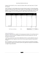
Application Temperature Sensing
On the right side of the QA450 application, you can see the temperature for both the left and right
channels. Generally, under normal operation, these temperatures must remain under 60C. Above 60C or
below 5C, the QA450 will disconnect the loads and require time to cool down or warm up. The sensors
are very accurate and respond very quickly. Generally, as long as you do not impart more than 300W of
power per channel, you do not need to worry about harming the QA450. It will self-protect. The
temperature readings are provided for information only.
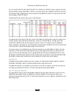
Application Current Sensing
The QA450 reports the current measured by the Current Sensing subsystem. The resolution is around 30
to 40 mA. That is, you will see readings jump by p/- 20 mA. For high-power amplifiers that might
draw 10A or so
, this generally isn’t a problem. Of c
ourse, if you want to measure an amp with a max
current of 100 mA, then this resolution can contribute significant errors.
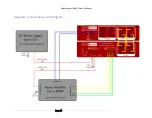
DUT Power
The DUT POWER button is used to the turn on the high-side PMOS in the QA450. When enabled, the S+
and S- will be connected by a low impedance of 25 mOhms or so. This is Rds(on) of the high-side PMOS
pass device.
If the QA450 application is closed or stops responding, or if the QA450 is disconnected from the USB,
then the QA450 will automatically open the load relays and disable the load power.


