


QuantAsylum QA450 User’s Manual
Page 5
Legal
This document and the associated computer codes, hardware design and hardware configuration files
are copyright © 2011 - 2018 by QuantAsylum USA LLC. All rights are reserved. You may share the
associated documents in PDF format freely. The EXE programs and code in the developer section is for
use only with QA products. The hardware and software designs are protected and the property of
QuantAsylum USA LLC.
In the Box
Your QA450 box contains the following:
•
QA450 Programmable Load
•
Power supply and Speaker connectors that mate with the QA450. These are installed on the
QA450 and can be removed by gently pulling.
Installation software, this manual, and application notes for the analyzer are available on the web at
http://www.QuantAsylum.com.
Important Things to Understand
Ground Reference
The QA450 USB interface shares a ground with the PC. The load portion and current sensing portion of
the analyzer does not. You should measure, and from time to time confirm, that the BNC grounds are
electrically isolated from the USB grounds.
This isolation is limited to 50V. Do not connect the QA450 to a product that has its ground reference
more than +/-50V from the PC ground.
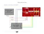
Current Sense Inputs
The QA450 has a 3-wire current sense connector (S+ from power supply, S- to DUT, and DUT GND) for
monitoring the high-side DC supply of an amplifier. The voltages on the S+ pin of this connector must
not exceed 50V DC and must be greater than 5V to ensure switching control. The DUT GND pin of this
connector must be connected to your DUT ground. All of these pins are isolated from the PC/USB
ground. Isolation is measured to be >10 GOhm at 1 KV.
WARNING:
Do not plug/unplug an amplifier power supply when using the current sensing AND the
green DUT LED is active. On very large amplifiers, this can cause hundreds of amps to flow for hundreds
of microseconds which may destroy the high-side switch. Always ensure the green LED is off before
connecting amplifiers. See the second below
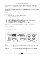
Load Inputs
The load inputs are isolated from the PC/USB subsystem and also from the current sense subsystem.
You will connect the amplifier outputs to the L- and L+ inputs for the left channel, and the R- and R+
inputs for the right channel.
Depending on your specified settings, the QA450 will present either a 4, 8 or open load to the amplifier.


