background image

7

QNET LABVIEW HINTS

7.1 SCALING SCOPES

This section describes a handy method of changing the x or y axis in a LabVIEW scope using

QNET

_

DCMCT

_

Swing

_

Up

_

Control

VI as an example. Read the steps below to reduce the y-axis range of the

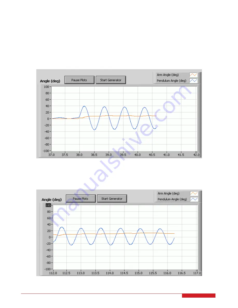
Angle (deg) scope shown in Figure 7.10 in order to see the blue trace more up close.

Figure 7.10: Scope needs to be scaled

1. As illustrated in Figure 7.11, to decrease the positive range of the scope down to 40, double-click on '100' in

the y-axis, type in '40', and press ENTER.

Figure 7.11: Scope needs to be scaled

QNET MYOELECTRIC- User Manual

14

Summary of Contents for QNET

Page 1: ...USER MANUAL QNET Myoelectric Trainer for NI ELVIS Set Up and Configuration Captivate Motivate Graduate...

Page 2: ...om This document and the software described in it are provided subject to a license agreement Neither the software nor this document may be used or copied except as specified under the terms of that l...

Page 3: ...4 Specifications 8 5 Environmental 9 6 Setup Guide 10 6 1 QNET and NI ELVIS II Setup 11 7 QNET LabVIEW Hints 14 7 1 Scaling Scopes 14 7 2 Saving Response 15 8 Troubleshooting 18 8 1 General Software...

Page 4: ...ear envelope filtering zero order hold position control and the basics of LabVIEW coding This is done using a PC with real time control capabilities and the NI ELVIS II The hardware of the MYOELECTRIC...

Page 5: ...nnector 10 Servo Motor Connector 3 EMG Power On Off SW2 Switch 11 Servo Motor 4 Battery Power Supply for EMG 12 Servo Clamps 5 PCI connector to NI ELVIS for interfacing QNET module with DAC 13 15V QNE...

Page 6: ...wn in Figure 3 4 the OPTO_OUT is the electromyogram signal that is measured by the EMG sensor and amplifier and offset by the isolation amplifier It is offset by about 2 5 V The 555 Timer resembles a...

Page 7: ...with a DAQ device is provided in Figure 3 3 The block diagram representing the circuit in the Myoelectric board is shown in Figure 3 4 Figure 3 3 Schematic of QNET Myoelectric trainer Figure 3 4 QNET...

Page 8: ...5 V Gain 300 V V Upper cut off frequency 500 Hz Lower cut off frequency 25 Hz Common mode rejection ratio 80 dB Supply voltage typical 5 00 V Isolation Amplifier VMAX Recommended input voltage accura...

Page 9: ...nit Operating temperature 15 to 35 C Humidity 20 to 90 Table 3 MYOELECTRIC environmental operating conditions Caution Ensure the unit is operated under the temperature and humidity conditions given in...

Page 10: ...setup procedure for using a QNET with an NI ELVIS II Figure 6 5 Connecting a QNET Trainer Caution Do not position the ELVIS II so that it is difficult to disconnect the main power Caution If the equip...

Page 11: ...he installation procedure are located and marked by an ID number in Figure 6 6 and described in Table 4 6 1 1 ELVIS II Components Figure 6 6 Components on ELVIS II ID Description 1 NI ELVIS II 2 Proto...

Page 12: ...ELVIS II power cable 4 Connect the ELVIS II USB cable to the PC 5 Connect the supplied QNET transformer to the QNET power jack on the QNET module 6 Connect the myoelectric sensor and grounding straps...

Page 13: ...6 8 QNET LEDs should all be ON 11 Power ON the myoelectric sensor power 12 Ensure that the Battery ON LED is lit as shown in Figure 6 9 Figure 6 9 Battery LED should be ON QNET MYOELECTRIC User Manual...

Page 14: ...e steps below to reduce the y axis range of the Angle deg scope shown in Figure 7 10 in order to see the blue trace more up close Figure 7 10 Scope needs to be scaled 1 As illustrated in Figure 7 11 t...

Page 15: ...0 10 0 However when changing the x axis i e the time scale it is recommended to do the following 1 Pause the scopes or stop the VI and clear the chart right click on scope select Data Operation Clear...

Page 16: ...e 7 14 opens and gives various image export options One way is to export the image to the clipboard as a bitmap This can then be pasted in a graphical software e g MS Paint Irfanview and saved to a de...

Page 17: ...5 Figure 7 15 Sample saved response The scope can be saved whether or not the VI is running However typically it is easier to stop the VI when the desired response is collected and then export the ima...

Page 18: ...wer switch which is located on the back of the ELVIS I and II units and the Prototyping Board Power switch which is situated on the front panel of the ELVIS I and on the top right corner of the ELVIS...

Page 19: ...ms and select the NI ELVIS II device 4 As shown in Figure 8 16 click on the Reset Device button 5 Once successfully reset click on the Self Test button 6 If the test passed reset the ELVIS II i e shut...

Page 20: ...pport link Fill in the form with all the requested software and hardware information as well as a description of the problem encountered Also make sure your e mail address and telephone number are inc...

Page 21: ...QNET 2 0 Rotary Pendulum Board teaches classic pendulum control Quanser QNET add on boards for the NI ELVIS platform teach introductory control topics in undergraduate labs cost effectively All QNETs...

Reviews: