background image

Chapter 5 

31 

KPC-1530/ 1730 User’s Manual 

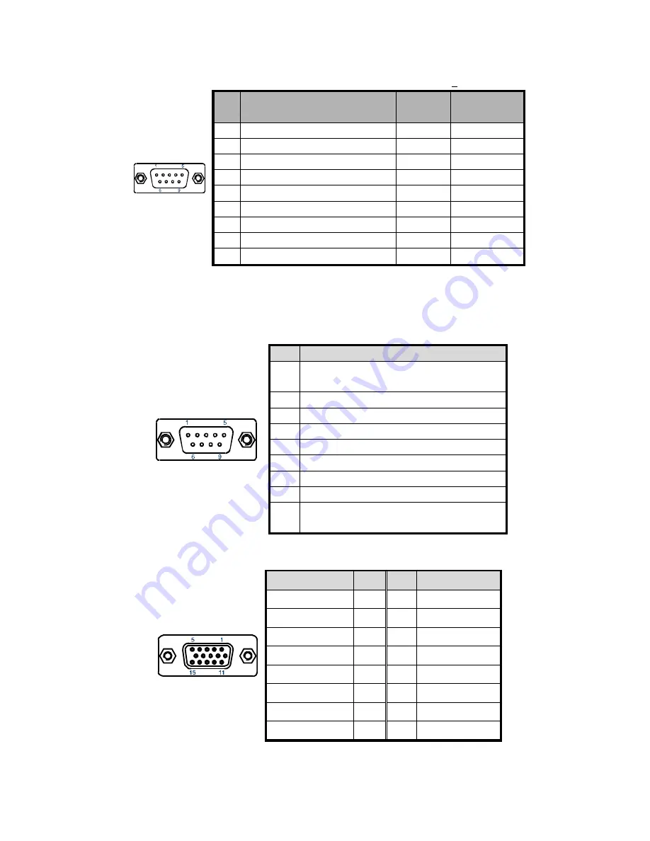
Table 5 COM1 RS-232/422/485 Connector (DB9)


Pin 

RS232  

RS422 

RS485  

Half Duplex 

DCD, Data carrier detect 

TX- 

DATA- 

RXD, Receive data 

RX+ 

N/A 

3 TXD, 

Transmit 

data 

TX+ 

DATA+ 

DTR, Data terminal ready 

RX- 

N/A 

5 GND, 

ground  GND 

GND 

DSR, Data set ready 

N/A 

N/A 

RTS, Request to send 

N/A 

N/A 

CTS, Clear to send 

N/A 

N/A 

RI, Ring indicator (+5V / +12V *)

N/A 

N/A 

* Voltage can be selected JP4. 

COM1 Function Type RS232/422/485 can be selected from BIOS setting. 


Table 6 COM2-4 RS-232 Connector (DB9) 


Pin

Signal 

+5V / +12V / DCD, Data carrier detect 
Note

Selected by JP5-7 

RXD, Receive data 

DTR, Data terminal ready 

4 GND, 

ground 

5 TXD, 

Transmit 

data 

DSR, Data set ready 

RTS, Request to send 

CTS, Clear to send 

+5V / +12V / RI, Ring indicator 
Note

Selected by JP5-7 


Table 7 VGA Connector (DB15) 


Signal Name 

Pin

Pin

Signal Name 

Red 1 

Green 

Blue 3 

NC 

GND 5 

GND 

GND 7 

GND 

VCC 9 

10 

GND 

NC 11 

12 

DDC2B 

data 

HSYNC 13 

14 

VSYNC 

DDC2B clock 

15 


Summary of Contents for KPC-1530

Page 1: ...I KPC 1530 1730 User s Manual KPC 1530 1730 Fanless Industrial Panel PC with Intel Atom N270 Intel 945GSE ICH7 M User s Guide...

Page 2: ...registered trademarks and trade names used in this user s guide are the property of their respective owners All rights reserved This user s guide contains information proprietary to Quanmax Customers...

Page 3: ...our Computer 10 Chapter 1 Introduction 13 Overview 13 Product Specifications 14 Mechanical Layout 15 Chapter 2 Assembly Disassembly 18 Accessing Internal Components 18 Memory Module Installation 19 In...

Page 4: ...Mechanical Internal Layout 19 Figure 7 Align the SO DIMM Memory Module with the onboard socket 19 Figure 8 Press down on the SO DIMM Memory Module to lock it in place 20 Figure 9 PCI card height restr...

Page 5: ...Connector 30 Table 4 LAN Ethernet RJ 45 Connector 30 Table 5 COM1 RS 232 422 485 Connector DB9 31 Table 6 COM2 4 RS 232 Connector DB9 31 Table 7 VGA Connector DB15 31 Table 8 CN 10 PS 2 KB MS Connecto...

Page 6: ...ser s guide for precautions and procedures If you have any questions please contact Quanmax Post Sales Technical Support WARNING High voltages are present inside the chassis when the unit s power cord...

Page 7: ...an ESD workstation and follow proper ESD procedure to reduce the risk of damage to components Quanmax strongly encourages you to follow proper ESD procedure which can include wrist straps and smocks...

Page 8: ...immediately 3 Inspect the product for damage If there is damage notify Quanmax customer service immediately Refer to Warranty Policy for the return procedure Regulatory Compliance Statements This sect...

Page 9: ...se if any repairs have been attempted by anyone other than Quanmax or its authorized agent or if the failure is caused by accident acts of God or other causes beyond the control of Quanmax or the manu...

Page 10: ...f data of any kind or for any direct indirect incidental or consequential damages in connection with or arising out of the performance or use of any product furnished hereunder Quanmax s liability sha...

Page 11: ...s with internal pressure such as electrolytic capacitors to fail or perform at reduced efficiency Power Protection The greatest threats to a system s supply of power are power loss power spikes and po...

Page 12: ...the UPS system UPS systems range in price from a few hundred dollars to several thousand dollars with the more expensive unit s allowing you to run larger systems for a longer period of time when AC p...

Page 13: ...provide a compact high performance human machine interface with optimal shock vibration and temperature resistance for tough industrial demands Check list 1 Take out the KPC 1530 1730 from the carton...

Page 14: ...1x Power On Off Switch 1x Power Connector Mic in Line in Line out 1x GbE RJ 45 4x USB 2 0 1x VGA 4x COMs with 5V 12V Power Selection COM1 RS 232 422 485 COM2 3 4 RS 232 1x PS 2 Keyboard Connector 1x...

Page 15: ...nual Mechanical Layout Front and Side Panel Figure 1 Mechanical Layout Front and Side WARNING Be sure not to block any air vents on the computer Blocked air vents can cause thermal problems I O Panel...

Page 16: ...Chapter 1 16 KPC 1530 1730 User s Manual Mechanical Dimensions Figure 3 Mechanical Dimensions KPC 1530...

Page 17: ...Chapter 1 17 KPC 1530 1730 User s Manual Figure 4 Mechanical Dimensions KPC 1730...

Page 18: ...t 3 to 5 minutes to let the computer cool before removing the computer cover Follow the procedure described below to access the system s internal components 1 Place the system front side down on a sof...

Page 19: ...DIMM 2 Do not touch the connectors of the SO DIMM Dirt or other residue may cause a malfunction 3 To make sure the correct DDR2 SO DIMM notches should match with the DDR2 SO DIMM 4 Hold the SO DIMM w...

Page 20: ...st be populated with memory modules of the same size and manufacturer Installation PCI Card NOTE When adding or removing expansion cards make sure that you unplug the power supply first Meanwhile read...

Page 21: ...described below to install a PCI card 1 Remove the PCI raiser card holder 1 and PCI slot cover 2 by loosening the retaining screw as shown 2 Fully insert the PCI card into the PCI raiser card 3 Repla...

Page 22: ...et and secure the HDD bracket to the ODD bracket Step 1 Remove the pre cut bracket opening of ODD and the PCI raiser card holder Loosen the 4 screws and take off the ODD bracket form the system Step 2...

Page 23: ...1530 1730 User s Manual VESA Mounting The product comes with VESA FDMI 75 100 standard mounting holes as shown below Use 4 screws with the appropriate length for your mounting bracket Figure 11 Mounti...

Page 24: ...ESA kit to the panel PC using the 4 screws Step2 Install the wall mount kit to the proper place of the wall by using the 6 screws Step3 Attach the panel PC to the wall mount kit which has been well fi...

Page 25: ...nel Mounting The Panel PC can be panel mounted and comes with brackets and screws for this purpose The required cutout for panel mounting and maximum panel thickness is shown below Figure 13 Panel Mou...

Page 26: ...ack and forth until they break free from the chassis KPC 1530 9 Bracket Opening Covers KPC 1730 10 Bracket Opening Covers Step2 Install the Panel Mount Seal on the inside edge of the Panel PC Step3 In...

Page 27: ...rong grounding type receptacle AC Power 1 Connect the supplied AC power cord to the system AC power inlet on the I O panel of the system 2 Connect the other end of the AC power cord to a corresponding...

Page 28: ...r distribution to the DC power feed wires 7 Press the power button to turn it on Operating System and Drivers If your product does not come with an operating system pre installed you will need to inst...

Page 29: ...ng correctly Occasionally wipe the system with a soft dry cloth You should only remove persistent dirt by use of a soft slightly damp cloth use only a mild detergent Make sure the ventilation holes ar...

Page 30: ...0 Type A Connector Pin Signal Name Pin Signal Name 1 5V 5 5V 2 USBx 6 USBx 3 USBx 7 USBx 4 GND 8 GND Table 4 LAN Ethernet RJ 45 Connector Pin Signal Pin Signal 1 Tx 5 NC 2 Tx 6 Rx 3 Rx 7 NC 4 NC 8 NC...

Page 31: ...N A N A Voltage can be selected JP4 COM1 Function Type RS232 422 485 can be selected from BIOS setting Table 6 COM2 4 RS 232 Connector DB9 Pin Signal 1 5V 12V DCD Data carrier detect Note Selected by...

Page 32: ...1 5V 5 7 Short Pin 1 of COM1 5V 7 9 Short Pin 1 of COM1 DCD RS232 TX RS422 DATA RS485 Default 2 2 4 Short Pin 9 of COM1 12V 4 6 Short Pin 9 of COM1 5V 6 8 Short Pin 9 of COM1 5V 8 10 Short Pin 9 of CO...

Page 33: ...Chapter 5 33 KPC 1530 1730 User s Manual Figure 15 Jumper and Connector Locations...

Reviews: