501510 Rev. S
Field
–
Replaceable Units (FRUs)
7-21
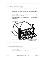
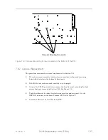
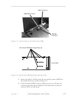
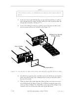
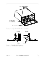
SENSOR Connector
EXEC Connector
DRVBAY
Connector
Figure 7-12 Top Connectors on the Interconnect PCBA
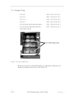
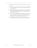
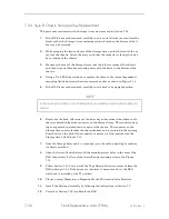
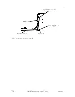
Interconnect PCBA Mounting Screws (8)
Front of RLS
Figure 7-13 Interconnect PCBA Mounting Screws (Left Side)
8.
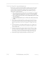
Remove the eight No. 1 Phillips screws that secure the Interconnect PCBA from
the left side of the chassis as shown in Figure 7-13.
9.
Lift the Interconnect PCBA up and out slightly to gain access to the cable con-
necting it to the Control Panel. Unplug the Control Panel cable and lift the In-
terconnect PCBA out of the chassis.
Summary of Contents for RLS-4470
Page 1: ...RLS 8000 Tape Library Technical Service Manual 501510 Rev S...
Page 2: ......
Page 14: ...xiv 501510 Rev S This page left blank intentionally...
Page 16: ...1 2 Introduction 501510 Rev S Table 1 1 Applicable Documents...
Page 20: ...1 6 Introduction 501510 Rev S This page left blank intentionally...
Page 23: ...501510 Rev S Description and Theory of Operation 2 3...
Page 34: ......
Page 50: ...3 16 The Operator Interface 501510 Rev S This page left blank intentionally...
Page 64: ...4 14 The Maintenance Menu 501510 Rev S This page left blank intentionally...
Page 65: ...501510 Rev S The Private Menu 5 1 5 The Private Menu...
Page 69: ...501510 Rev S The Private Menu 5 5 10 Close the Front Panel Door...
Page 188: ...8 10 Firmware Updating 501510 Rev S Figure 8 7 Properties Screen...
Page 205: ...501510 Rev S RLS Expansions 9 13 This page left blank intentionally...

