background image

page 10

Appendix A

Installing Pro9 system using existing cabling to connect the base station to the DTM located in 
the order point (Q-P9NTB x2)

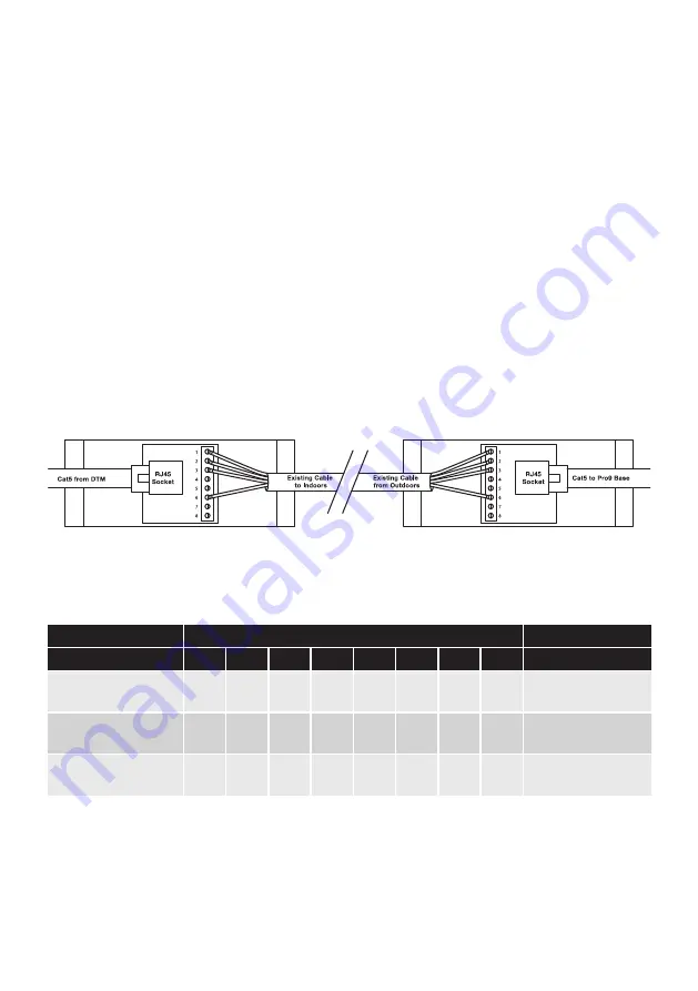
Using the network termination boxes allows existing cabling to carry digital signals and power on 
previously installed cabling. Inside each is a small PCB with a network adaptor socket and screw 
terminals, as below. Follow the steps below to make the correct connections. 

1.  Make and test 2 Cat5 patch leads at a length suitable for use, one inside and one outside.  (You may 
use bought Cat5 patch leads if preferred.) Fully test these leads.

2.  Outside, strip back your existing cable and connect into the screw terminals of one of the network 
termination boxes.  Follow the colour codes in the table below.

3.  Inside, again strip back the other end of your existing cables and connect into the second network 
termination box. Follow the colour codes in the table below.

4.  At the order point connect your Cat5 lead from the DTM into the network termination box.

5.  Outside, connect the second Cat5 lead from the network termination box to the base station.

Different types of existing cables should be connected as follows.

Terminal connection

Cable type

1

2

3

4

5

6

7

8

Notes

4 core overall screened 
22A WG with drain

red

black

white

nc

nc

green

nc

nc

As used in many DT 
installations

Specialist DT cable 3 pair 
individually screened

red

black

white

nc

nc

blue

nc

nc

Specialised cable 
designed for DT

Multi pair screened cable 
22A WG (use two pairs)

red 

(pr1)

black 

(pr1)

white 

(pr2)

nc

nc

black 

(pr2)

nc

nc

General purpose cable 
suitable for DT

Figure 14 - Connecting using existing cabling to DTM in speaker post

Summary of Contents for Pro9

Page 1: ...Pro9 Headset System Installation Manual...

Page 2: ...point Q P9NTB x2 Appendix B Installing Pro9 system using existing cabling to page 11 connect the base station to the DTM located in the building Q P9JB x2 Appendix C Pro9 auxiliary connections Q P9AC...

Page 3: ...lity clarity and acts as a shield from external interference If you are unfamiliar with Quail Digital products you are encouraged to watch our training films on this product before you start the insta...

Page 4: ...reen when fully charged On occasion new batteries may get warm during charging If this happens the LED will go out and charging will stop to protect the battery until it cools down this is normal Step...

Page 5: ...core test Figure 4 shows the colour code sequence for wiring the plug Step 8 Plug in the Cat5 cable and the speaker and the microphone to their respective sockets on the DTM as shown Step 9 Before con...

Page 6: ...as much clear space around it to optimize the transmission range Use the template to locate the fixing holes The power supply should be close by Step 12 If there is a lane timer and or a chime speaker...

Page 7: ...when registered Repeat this process one at a time until each headset is registered Step 15 To test the audio link to the order point have someone go out to the order point Press vehicle detection over...

Page 8: ...the local environment To do this you need to access the Pro9 settings menu as below which you do via your laptop or cellphone see Appendix F and G for access Step 18 Ask someone in a vehicle to drive...

Page 9: ...runner can take over as order taker by pressing and holding I and until their boom LED double pulses green When a vehicle arrives they should press I They re now the order taker and the previous order...

Page 10: ...odes in the table below 3 Inside again strip back the other end of your existing cables and connect into the second network termination box Follow the colour codes in the table below 4 At the order po...

Page 11: ...existing audio cable to section B of the PCB as shown 5 Then go to the other end of the audio cable in the building and use the other junction box to attach the speaker and microphone plugs to it page...

Page 12: ...ption Notes 1 White Chime speaker ve For connection directly to a speaker to provide a chime on arrival of a vehicle at the order point 2 Red Chime speaker ve 3 Blue Timer out common 0v switch output...

Page 13: ...you lose connection 2 Set up the repeater in the area where you need further coverage connecting the Cat5 cable from the base station to the repeater Connect up 3 Check that you have enough coverage...

Page 14: ...vided as a guide for the screw locations 3 Plug the Cat5 cable to the IN port of the table service base station 4 Return to the drive thru base station and disconnect the power 5 Plug in the new Cat5...

Page 15: ...indows button on your keyboard and select the settings cog 2 Select Network and Internet 3 Select Ethernet then Change adaptor options 4 Right click on your ethernet connection and click Properties 5...

Page 16: ...WiFi bridge This device is a tool for the engineer and once setup can be used on any Pro9 system to connect to the installer API http en vonets es products VAP11G 300 1 Unpack the Vonets WiFi bridge a...

Page 17: ...ur laptop To use the wireless adaptor you will need a power supply or battery pack to power the unit a standard USB charger power supply or battery pack will suffice Once powered plug the RJ45 into th...

Page 18: ...ion is connected to the first order point and connect a short Cat5 cable from the OUT port of this base station to the IN port of the second base station 3 Re connect the power to BOTH base stations T...

Page 19: ...n from the left engages Single Order Taker mode where a single order taker operates both lanes Its default position off is one order taker for each order point Single order taker mode Action Standby C...

Page 20: ...a preferred audio voice recorder then rename the recorded files to the required name in a known location of your computer 2 Audio files need to be saved in mono single track and be encoded as U Law at...

Page 21: ...n c 4 Once connected to the Quail Pro9 base station see Appendix F use the link in System Setup 2 Section 5 Tandem Mode to upload your file to the base station 5 Using the link Play check that your me...

Page 22: ...aker in order point has failed Microphone in order point has failed First check cable is plugged in on top of base station if it is Send Tech to site to repair or replace loop Send Tech to site to rep...

Page 23: ...page System Setup 2 go to Registration select YES then click Submit ALL headsets registered to that base station will deregister the headset LED will flash RED with a single beep every second Single...

Page 24: ...asing is cracked or otherwise damaged isolate it and dispose of in an approved manner Batteries should always be either in the charger OR in a headset Do not leave batteries out on worktops or other p...

Page 25: ...nge no change table service page lane 1 runner lane 2 runner no change Boom LED solid white single pulse green single pulse blue Sound single beep single beep single beep triple beep Original headset...

Page 26: ...l Base Station FCC ID UDDQP9BS This device complies with Part 15 of the FCC Rules Operation is subject to the following two conditions 1 This device may not cause harmful interference and 2 this devi...

Page 27: ...closure IP64 15watts 30 peak 8 ohms 210 to 7000 Hz 4 pin GX16 connector 117x117x73mm without bracket 682g Pro9 Charger Q P9CH 8 port Power light Individual battery status lights 205x325x45mm 710g Pro9...

Page 28: ...Quail Digital 92 Lots Road London SW10 0QD United Kingdom www quaildigital com 28 July 2020...

Reviews: