Quadra-Fire CB1200M-MBK Owner'S Manual Download Page 24

 24 


                        7014-259B 


       November 30, 2017

CB1200 FREESTANDING

Reference Materials

2.  Convection Blower

The convection blower is mounted at the bottom rear of the 

appliance.  There are 2 impellers, one on each side of the 

motor.  The convection blower pushes heated air through the 

heat exchange system into the room.  

3.  Combustion (Exhaust) Blower

The combustion blower is mounted on the lower left side on 

rear of appliance.  The blower is designed to pull the exhaust 

from the appliance and push it out through the venting system.  

4.  Feed System

The feed system is located in the hopper under the feed 

motor cover box on the left side of the appliance and can 

be removed as an entire assembly.  The assembly includes 

the feed motor, mounting bracket, bearing and feed spring 

(auger).  The hollow feed spring (auger) pulls pellets up the 

feed tube from the hopper area and drops them down the 

feed chute into the fire pot.  

5.  Fire pot

The fire pot is made of high quality ductile iron and has a 

cleaning  pull-out  rod.   The  floor  of  the  fire  pot  opens  for 

cleaning when you pull out the rod.  Be sure that the floor 

returns to a completely closed position or your appliance will 

not operate properly.

6.  Fuse

The fuse is located on the front of the junction box on the right 

side of the appliance.  The fuse will blow should a short occur 

and shut off power to the appliance.

7. 

Heat Exchangers

The heat exchangers transfer hot air from the exhaust system 

into convection air. Lift the appliance top to access the heat 

exchangers.  There are 2 clean out rods located under  the 

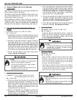
When describing the location of a component, 

it is always AS YOU FACE THE FRONT OF 

THE APPLIANCE.

A. Component Functions 

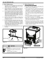
1.  Control Box

  a.  The control box is located under a small cover in the 

right rear corner of the inside of the hopper.

  b. There is a  light located inside of the control box. The 

internal light will turn green when the appliance has 

reached a temperature of 200°F (93°C) in the fire pot 

and will turn red when it reaches 600°F (315°C).

   c. There is also an internal blue light located in the upper 

left corner of the control box.  When you plug in the 

appliance the blue light will automatically start blinking 

1 blink every 10 seconds for the first 60 seconds and 

then will stop. 

E

NOTE:

Do 

NOT

 open the control box.  This will void the 

warranty.  If you need to plug in or remove the control 

box  you must first

 unplug the appliance.

heat exchangers.  

8

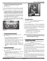
Heat Output Switch

The heat output switch is located on the upper right side panel.  

The function of the heat output switch is to regulate the burn 

rates; low, medium, and high settings.

9.  Hopper Switch

The hopper switch is located in the upper right hand corner 

of the hopper.  This switch is designed to shut down the feed 

motor whenever the hopper lid is opened.

10. 

Igniter

The igniter is mounted on the base of the fire pot.  Combustion 

air travels over the red hot igniter creating super heated air 

that ignites the pellets. 

11.  J

unction Box And Wiring Harness

The junction box is located on the right side of the appliance, 

behind the interior shield.  The junction box and wiring harness 

are replaced as one component.

12.  Power Supply

The power outlet is located on the back of the appliance, lower 

right corner.  Check the wall receptacle for 120 volt, 60 Hz 

(standard current).  Make sure the outlet is grounded and has 

the correct polarity.  A good surge protector is recommended.

13. 

Red Call Light

The red call light is on the front of the junction box, next to the 

reset button.  The function of the red call light is to indicate 

that the thermostat is calling for heat.

14.  Reset Button

The reset button is located on the right side of the appliance 

next to the red call light.  The function of the button is to 

momentarily open the thermostat circuit, which restarts the 

system.  

15.  Thermocouple

The  thermocouple  is  located  on  top  of  the  fire  pot  inside 

the  thermocouple  cover  (ceramic  protection  tube).  The 

thermocouple sends a millivolt signal to the control box 

indicating the preset temperatures of the green and red lights 

have been obtained.

16.  Thermostat

The appliance is designed to run on a 12 volt AC thermostat. 

The heat anticipator should be set on the lowest setting 

available. 

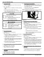
17. 

Snap Disc #1 (Convection Blower) 145°F

Snap disc #1 is located on the right side of the appliance on 

the top of the heat exchanger box.  There are 2 purple wires 

connected to it.  This snap disc turns the convection blower on 

Summary of Contents for CB1200M-MBK

Page 1: ...until it is cooled NEVER allow children to touch glass Keep children away CAREFULLY SUPERVISE children in same room as fireplace Alert children and adults to hazards of high temperatures High tempera...

Page 2: ...et appareil une chemin e servant un autre appareil Utilisez syst m de ventilation L ou P diam tre 76mm ou 102mm C C D B E E A B C C Listed Solid Fuel Room Heater Pellet Type Insert Also suitable for M...

Page 3: ...ons 7 A Fire Safety 7 B Non Combustible Materials 7 C Combustible Materials 7 D Fuel Material and Fuel Storage 7 E Before Your First Fire 8 F Filling the Hopper 8 G General Operating Information 8 H S...

Page 4: ...home construction warranty coverage begins on the date of first occupancy of the dwelling or six months after the sale of the product by an independent authorized HHT dealer distributor whichever occu...

Page 5: ...does not cover the following Changes in surface finishes as a result of normal use As a heating appliance some changes in color of interior and exterior surface finishes may occur This is not a flaw...

Page 6: ...lets 1 Listing and Code Approvals A Appliance Certification NOTE Hearth Home Technologies manufacturer of this appliance reserves the right to alter its products their specifications and or price with...

Page 7: ...ce material it may have a high or low ash content Higher Ash Content Material Hardwoods with a high mineral content Fuel that contains bark Standard grade pellets high ash pellets Lower Ash Content Ma...

Page 8: ...igher ash content requires the ash drawer to be emptied more frequently Hardwoods require more air to burn properly Premium wood pellets produce the highest heat output Burning pellets longer than 1 1...

Page 9: ...and seems somewhat lazy the feed rate will need to be reduced This is done by sliding the fuel adjustment control rod down which will reduce the feed If the fire is not 4 to 6 inches 102 to 152mm tal...

Page 10: ...ce will start on its own without need for priming providing the control system is asking for heat 2 The appliance will always go through a normal shut down sequence before restarting There is a 4 scre...

Page 11: ...remove Press and pull to remove Figure 11 3 Power Outlet Terminal Block Center 2 screws for Thermostat Wires Figure 11 1 Thermostat Operation Digital display Digital display Back light Heat On or Off...

Page 12: ...ssive build up of ash The lower burn settings will produce more ash the higher burn settings produce less The more it burns on low the more frequent clean ing of the glass is required 4 Fire has tall...

Page 13: ...ur if appliance is not cool before unplugging Risk of shock if appliance not unplugged before servicing appliance CAUTION Cleaning or Inspection Frequency Daily Weekly Monthly Yearly Ash Pan Wood Pell...

Page 14: ...er on its cycle time It will pull fly ash out the exhaust instead of into the room WARNING Fire Risk NEVER pull fire pot cleaning rod or cleaning slide plates out when appliance is operating The clean...

Page 15: ...wer is off b Remove access door on the right of the appliance 4 screws c Use a small vacuum hose attachment to clean area d Re install and close trap door 9 Cleaning the Hopper Frequency Monthly or af...

Page 16: ...Lubrication Frequency Yearly or as needed By Qualified Service Technician Task Contact your local dealer 15 Cleaning the Top Vent Adapter a The appliance must be in complete shutdown and the exhaust b...

Page 17: ...the fire pot with pellets which may result in smoking sooting and possible hopper fires Figure 17 4 shows an example where the fire pot overfills pellets back up into the feed tube and ash has accumu...

Page 18: ...ontrol box Call light on No fire Partially burned fuel in fire pot Fire pot clean out plate not closed Fire pot is dirty missed ignition Check that fire pot clean out plate is fully closed Clean fire...

Page 19: ...loss of vacuum Empty hopper of fuel Use a wet dry vacuum cleaner to remove remaining fuel from hopper including feed tube Check feed chute for obstructions Loosen 2 screws and jiggle feed assembly Ch...

Page 20: ...ick panels Change fuel brand to pre mium Check that fire pot clean out plate is fully closed Reduce feed rate using feed rate adjustment control rod located inside hopper Nuisance shutdowns Low flame...

Page 21: ...TE When removing the side glass with the door latch you must remove the door latch first before removing the side frame Use a powered Phillips head screw driver to remove the 4 screws a Be sure the ap...

Page 22: ...procedures to shut down the appliance and let it completely cool down and then unplug it and remove the ash drawer 2 Follow instructions to remove the ash pan found on page 14 Remove the access plate...

Page 23: ...ng Re install blower to blower housing i Install blower on housing ensuring that wiring exits facing the 8 o clock position Place the washer and then the grounding wire on nearest mounting plate stud...

Page 24: ...the appliance the blue light will automatically start blinking 1 blink every 10 seconds for the first 60 seconds and then will stop E NOTE Do NOT open the control box This will void the warranty If yo...

Page 25: ...r cover box from inside the hopper If the fire tries to burn back into the feed system or push exhaust up the feed tube this snap disc will shut the entire system off This disc must be manually reset...

Page 26: ...erminal Block Center 2 screws for Thermostat Wires Cleaning Rods Heat Exchanger Tubes Figure 26 1 Figure 26 2 Figure 26 3 Heat Output Fan Speed Reset Button Call Light HIGH HIGH MED LOW LOW Outside Ai...

Page 27: ...November 30 2017 7014 259B 27 CB1200 FREESTANDING C Service and Maintenance Log Date of Service Performed By Description of Service...

Page 28: ...28 7014 259B November 30 2017 CB1200 FREESTANDING Date of Service Performed By Description of Service...

Page 29: ...ginning Manufacturing Date April 2009 Ending Manufacturing Date Active Classic Bay Freestanding Pellet Stove 1 5 2 3 6 7 12 9 8 4 10 11 13 14 15 16 21 17 18 19 20 22 23 24 25 26 33 35 37 38 39 40 31 2...

Page 30: ...umper Rubber Pkg of 12 SRV224 0340 12 Y Bushing Hopper Lid Qty 2 812 1010 1 3 Top Assembly Top Only SRV410 4980 Hopper Lid Magnetic Switch SRV7000 375 Y Wire Harness SRV414 1220 Y 2 1 Baf e Assembly L...

Page 31: ...30 Y 10 3 Thermocouple Cover Qty 1 812 1322 Y Pkg of 10 812 4920 Y 10 4 Thermocouple 812 0210 Y 10 5 Thermocouple Bracket W Set Screw 812 3171 Y 10 6 Heating Element Assembly 18 Loop Igniter Qty 1 SRV...

Page 32: ...21 Latch Magnet 229 0631 18 Mount Side Curtain Right 410 5261 19 Curtain Side Right 812 3800 20 Latch Draw 229 0640 Y 21 Snap Disc Convection Blower 1 SRV230 0060 Y 22 Convection Blower 130 60 CFM 812...

Page 33: ...distributor Stocked at Depot ITEM DESCRIPTION COMMENTS PART NUMBER 39 Feed Motor Assembly 812 3690 Y Bearing Feed System Nylon SRV410 0552 Y 39 1 Screw 8 32 X 3 8 PH Pkg of 40 225 0500 40 Y 39 2 Feed...

Page 34: ...isc Mounting 7005 253 Call Light Fluorescent New Style Junction Box SRV7000 122 Component Pack 812 3630 Cleanout Tool 414 1140 Y Harness Thermostat Wire 230 0810 Paint Touch Up 4 oz 812 0910 Power Cor...

Page 35: ...7040 Cover Outside Air Kit Floor 411 1071 Hose Alum Flex 2 Inch x 3 Ft Qty 3 Ft Req SRV200 0860 Outside Air Cap Assembly 7001 044 Outside Air Collar Assembly SRV7001 045 Trim Plate Outside Air Kit 41...

Page 36: ...e purchased installed _________________________________________________________________________ Serial Number ____________________________________ Location on appliance ___________________________ Dea...

Reviews: