Quadra-Fire CASTILE-MBK-B Installation Manual Download Page 20

 20 


                        7021-154J 


   May 12, 2017

CASTILE FREESTANDING

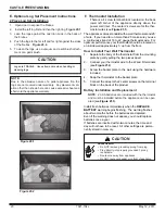
E. Optional Log Set Placement Instructions 

2 Piece Log Set Installation

1.


Open door to expose the firebox.

2.  Install

 the 

left

 log 

first and then the right log. 

Figure 20.1

3.  Lean the logs against the cast iron brick in the back of 

the firebox.

4.  Push the logs to the far left and far right against the sides 

of the firebox.  

Figure 20.2.

5.  To clean the logs, use a vacuum and a soft brush attach

-

ment or a paint brush.

Figure 20.2

Figure 20.1

CAUTION

Logs are FRAGILE.  Use extreme care when handling or 

cleaning logs.

NOTE:


Due  to  the  abrasive  nature  of  a  pellet  appliance  fire,  the 

logs are not covered under warranty.  Any placement vari

-

ation other than shown here can cause excessive heat and 

shall void the appliance warranty.

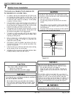
F.  Thermostat Installation


There is a 4 screw terminal block located on the back 

lower  left  corner  of  the  appliance  directly  above  the 

power cord inlet.  The center 2 screws are for the ther

-

mostat wires (see 

Figure 21.1

). 

Shock hazard.

•  Do NOT remove grounding prong from plug.

•  Plug directly into properly grounded 3 prong 

receptacle.

•  Route cord away from appliance.

• 

Do NOT route cord under or in front of appliance.

CAUTION

The appliance comes standard with a wall thermostat and 25’ 

of wire.  If you need to run more than 25’ make sure you use 

a continuous strand of 18 to 22 gauge thermostat wire.  For 

optimum performance your thermostat should be located on 

an inside wall approximately 5’ up from the floor.

How to Install Your Wall Thermostat


1.    Separate the body of the thermostat from the mounting 

plate by gently pulling the two pieces apart

2.  Connect your thermostat wire to the W and R terminals 

(see 

Figure 21.2

)

3.  Screw the backer plate to the wall using the hardware 

included

4.  Snap the thermostat to the backer plate
5.  Connect the wires to the 2 center screws on the terminal 

block on the back of the product

Battery Installation and Replacement


NOTE:  

2 AAA batteries are included with the thermostat 

and must be installed before the appliance can be oper

-

ated 

(see 

Figure 21.3

)

.


Install fresh batteries immediately when the 

REPLACE 

BATTERY 

warning begins flashing.  The warning flashes 

about two months before the batteries are depleted.

Even if the warning does not appear, you should replace 

batteries once a year.

If batteries are inserted within two minutes, the time and 

day will not have to be reset.  All other settings are perma

-

nently stored in memory.

Summary of Contents for CASTILE-MBK-B

Page 1: ...minimum clearances to combustibles as specified Failure to comply may cause house fire HOT SURFACES Glass and other surfaces are hot during operation AND cool down Hot glass will cause burns Do not to...

Page 2: ...Components 5 E Install Checklist 6 3 Dimensions and Clearances 7 A Appliance Dimensions 7 B Clearances to Combustibles UL and ULC 8 C Hearth Pad Requirements UL and ULC 8 D Alcove 9 4 Vent Informatio...

Page 3: ...ped with 5mm ceramic glass Replace glass only with 5mm ceramic glass Please con tact your dealer for replacement glass D Electrical Rating 115 VAC 60 Hz Start 4 1 Amps Run 1 1 Amps E Mobile Home Appro...

Page 4: ...the installation Location of the appliance and chimney will affect performance Consideration must be given to Safety convenience traffic flow Placement of the chimney and chimney connector and to mini...

Page 5: ...ermostat Wall Control Location The thermostat wall control s location will have some affect on the appliance s operation Maximum wire length from appliance is 100 feet 30 48m with continuous non splic...

Page 6: ...the party responsible for use and operation ATTENTION INSTALLER Follow this Standard Work Checklist This standard work checklist is to be used by the installer in conjunction with not instead of the...

Page 7: ...7 3 Side View Figure 7 4 Side View with Top Vent Adapter 24 in 609mm 24 5 8 in 626mm 12 in 305mm 24 in 609mm 28 9 16 in 725mm 15 15 16 in 405mm 22 7 8 in 582mm 17 in 431mm 16 5 16 in 414mm 28 3 4 in...

Page 8: ...ecommended extending beneath the flue pipe when installed with horizontal venting or under the Top Vent Adapter with vertical installation CANADA INSTALLATIONS A non combustible floor pro tection exte...

Page 9: ...Illustrations diagrams are not drawn to scale Actual installation may vary due to individual design preference D Alcove Figure 9 1 All minimums listed are to a combustible surface Minimum Maximum Inc...

Page 10: ...protruding parts of the structure P 12 in Clearance above roof line for vertical terminations All minimum clearances are listed with an Outside Air Kit OAK installed unless otherwise noted in table be...

Page 11: ...t with your local HVAC professional to determine the ventilation demands for your house Vent Configurations To reduce probability of reverse drafting during shut down conditions Hearth Home Technologi...

Page 12: ...zontally from c Not less than 12 inches 305mm above 3 Distance from permanently closed windows a Not less than 12 inches 305mm below horizontally from or above 4 Distance between bottom of termination...

Page 13: ...2 If the equivalent length of pipe is 12 feet 3 7m with altitude of 6 000 feet 1829m you may use 3 or 4 inch 76 to 102mm diameter type L or PL vent H Pipe Selection Chart The chart will help you in de...

Page 14: ...cumulate ash and will need to be cleaned more often Try to keep them as short as possible ONE 90 ELBOW Total Horizontal Minimum Vertical Vent Diameter 4 0 3 5 5 3 6 6 3 7 7 3 8 8 4 9 9 4 10 10 4 11 11...

Page 15: ...stalla tions Must use 3 or 4 inch 76 102mm L or PL Listed pellet venting or Listed double wall pipe and a Quadra Fire Outside Air Kit in mobile homes NOTE In Canada where passage through a wall or par...

Page 16: ...an out Cover 24 in 610mm Minimum Ceiling Support 6 in 152mm Flue Connector 6 in 152mm Class A Chimney Connector Adapter 3 in to 6 in 76 152mm Top Vent Kit We recommend a minimum of 60 inches 1524mm ve...

Page 17: ...ce Concrete Cap 1 in 25mm clearance with firestop 6 in 152mm minimum Non combustible Hearth Pad Airtight clean out door Sheathing 2 in 51mm minimum Flashing 1 in 25mm clearance 1 in 25mm clearance wit...

Page 18: ...N Never draw outside combustion air from Wall floor or ceiling cavity Enclosed space such as an attic or garage Flex Hose Hose Clamp Collar Assembly Trim Ring Termination Cap Assembly Hose Clamp Air I...

Page 19: ...hort horizontal pipe in the top vent adapter as a guide Install the 4 screws Figure 19 2 6 Install the vent pipe into the top vent adapter be sure to silicone all joints C Rear Vent Rear Vent to Top V...

Page 20: ...from appliance Do NOT route cord under or in front of appliance CAUTION The appliance comes standard with a wall thermostat and 25 of wire If you need to run more than 25 make sure you use a continuo...

Page 21: ...S FOR THERMOSTAT WIRES POWER OUTLET FUSE Fuse W R Figure 21 2 Press and pull to remove Press and pull to remove Figure 21 3 Thermostat Operation Digital display Digital display Back light Heat On or O...

Page 22: ...3280 Part 24 NEVER INSTALL IN A SLEEPING ROOM WARNING Spark Arestor Cap Roof Flashing Storm Collar Joist Shield Firestop Double Wall Connector Pipe Figure 22 1 CAUTION Never draw outside combustion ai...

Page 23: ...ssembly 7001 044 Outside Air Collar Assembly SRV7001 045 Trim Plate Outside Air Kit 412 7100 Pullrod Handle PULLROD HNDL Smart Batt Il 841 0970 Smart Stat Il 841 0960 Thermostat Mechanical 812 3760 Y...

Page 24: ...purchased installed _________________________________________________________________________ Serial Number ____________________________________ Location on appliance ___________________________ Deale...

Reviews: