


10
7033-361B
November,
2021
4
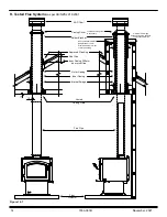
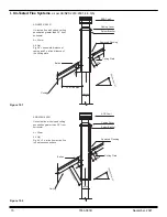
Chimney Systems
Recommended
Location
Marginal
Location
Location
Not
Recommended
Recommended
Location
Location NOT
Recommended
Multi-level Roofs
Windward
Leeward
Outside Air Kit Termination Cap
Figure 10.1
A. Locating Your Appliance & Chimney
Location of the appliance and chimney will affect
performance. As shown in
Figure 10.1
the chimney should:
• Install through the warm space enclosed by the building
envelope. This helps to produce more draft, especially
during lighting and die down of the fire.
• Penetrate the highest part of the roof. This minimizes
the affects of wind turbulence and down drafts.
•
Consider the appliance location in order to avoid floor
and ceiling attic joists and rafters.
• Locate termination cap away from trees, adjacent
structures, uneven roof lines and other obstructions.
Your local dealer is the expert in your geographic area and
can usually make suggestions or discover solutions that will
easily correct your flue problem.
Summary of Contents for 31M-ACC-AU
Page 19: ...19 7033 361B November 2021...


