background image

R1

P68 Pellet Stove Owners Manual

SAVE THESE INSTRUCTIONS.

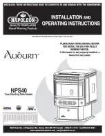
Installation &  Operating Manual

R3

“Ce manuel est disponible en Français sur demande”

SAFETY NOTICE

PLEASE READ THIS ENTIRE MANUAL BEFORE YOU INSTALL AND USE YOUR NEW ROOM HEATER.  FAILURE
TO FOLLOW INSTRUCTIONS MAY RESULT IN PROPERTY DAMAGE, BODILY INJURY, OR EVEN DEATH.

FOR USE IN THE U.S. AND CANADA.  SUITABLE FOR INSTALLATION IN MOBILE HOMES.

IF  THIS HARMAN  STOVE IS NOT  PROPERLY INSTALLED, A HOUSE FIRE MAY RESULT.  FOR YOUR SAFETY,
FOLLOW INSTALLATION DIRECTIONS.

CONTACT LOCAL BUILDING OR FIRE OFFICIALS ABOUT RESTRICTIONS AND INSTALLATION INSPECTION
REQUIREMENTS IN YOUR AREA.

CONTACT YOUR LOCAL AUTHORITY (SUCH AS MUNICIPAL BUILDING DEPARTMENT, FIRE DEPARTMENT,
FIRE PREVENTION BUREAU, ETC.) TO DETERMINE THE NEED FOR A PERMIT.

CETTE GUIDE D'UTILISATION EST DISPONIBLE EN FRANCAIS. CHEZ VOTRE CONCESSIONNAIRE DE HARMAN
STOVE COMPANY.

Evaluation notes were added to the output document. To get rid of these notes, please order your copy of ePrint IV now.

Summary of Contents for P68

Page 1: ...E U S AND CANADA SUITABLE FOR INSTALLATION IN MOBILE HOMES IF THIS HARMAN STOVE IS NOT PROPERLY INSTALLED A HOUSE FIRE MA YRESULT FOR YOUR SAFETY FOLLOW INSTALLATIONDIRECTIONS CONTACT LOCAL BUILDING OR FIRE OFFICIALSABOUT RESTRICTIONSAND INSTALLATION INSPECTION REQUIREMENTS INYOUR AREA CONTACT YOUR LOCAL AUTHORITY SUCH AS MUNICIPAL BUILDING DEPARTMENT FIRE DEPARTMENT FIREPREVENTION BUREAU ETC TODE...

Page 2: ...2 P68 Pellet Stove ...

Page 3: ...u need to do is set your desired room temperature and fill the hopper With the P68 you will notice even heat throughout your home and a level of convenience you never thought possible The P68 epitomizes the capability of Harman Pellet Stoves taking advantage of Harman s 20 years of pellet stove design technology and manufacturing This 68 000 BTU stove has the highest output smartest controls wides...

Page 4: ... should be done in accordance with the Manufactured Home and Safety Standard HUD CFR 3280 Part 24 DO NOT INSTALL IN SLEEPING ROOM WARNING CAUTION THE STRUCTURAL INTEGRITY OF THE MOBILE HOME FLOOR WALL AND CEILING ROOF MUST BE MAINTAINED CAUTION KEEP COMBUSTIBLE MATERIALS SUCH AS GRASS LEAVES ETC AT LEAST 3 FEET AWAY FROM THE FLUE OUTLET ON THE OUTSIDE OF THE BUILDING IMPORTANT NOTES ...

Page 5: ...st iron flame guide on top of the burn pot Make sure that the flame guide is fully seated on the vertical sides of the burn pot and that the back of the guide rests against the body of the stove INSTALL EXHAUST VENT AT CLEARANCES SPECIFIED BY THE MANUFACTURER Most pellet pipes require a minimum of 3 of clearance to combustible materials Rear Cover Panels Shipping Bolts Note These same holes are us...

Page 6: ...ation on the draft test procedure re fer to Page 19 Mobile Home Installation When installing this unit in a mobile home sev eral requirements must be followed 1 The unit must be bolted to the floor This can be done with 1 4 lag screws through the 2 holes in the base plate 2 The unit must also be connected to outside air See page 8 3 Floor protection and clearances must be fol lowed as shown 4 Unit...

Page 7: ...when measured fromthe horizontalcenter line of the regu lator 1 I The clearance to service regulator vent outlet must be a minimum of 6 feet 1 J The clearance to a non mechanical air sup ply inlet to the building or the combustion air inlet to any other appliance must be a minimum of 48 1 K The clearance to a mechanical air supply inlet must be a minimum of 10 feet 1 with outside air installed 6 f...

Page 8: ... sealedto the stove with high temp silicone caulking Vent Pipe Pellet venting pipe also known as PL vent is constructed of two layers with air space between the layers This air space acts as an insulator and reduces the outside surface temperature to allow a clearance to combustibles of only 3 inches The sections of pipe lock together to forman air tight seal in most cases However in some cases a ...

Page 9: ...utside air is mainly noticed in small very tight houses To installoutside air use 2 3 8 I D non com bustible flex pipe There is a break away hole on the rear panel of the P68 stove which must be removed before connecting the flex pipe The pipe should be run outside and terminate to the side or below the vent pipe outlet so the flue outlet is more than 12 from the inlet cover The maximum length run...

Page 10: ...ble materials such as grass leaves etc at least 3 feet away from the flue outlet on the outside of the building 1 Preferred method This method provides excellent venting for nor mal operation and allows the stove to be installed closest to the wall Two inches from the wall is safe however four inches allows better access to remove the rear panel The vertical portionof the vent should be three to f...

Page 11: ... into an existing fireplace chimney US only This method provides excellent venting for nor mal operation This method also provides natural draft in the event of a power failure If the chimney condition is questionable you may want to install a liner as in method 6 The chimney should be inspected and cleaned before installing your stove If you discover that the chimney does not have a clay tile lin...

Page 12: ...vent pipe fittings Seal pipe joints with silicone or aluminum tape in addition to the sealing system used by the manufacturer Pipe size should be in creased to 4 using this method 7 Installing into an existing chimney US and Canada This method provides excellent venting for nor mal operation This method also provides natural draft in the event of a power failure In Canada and some places in the US...

Page 13: ... 5 for cornerinstallation clearances Minimum flue vent configuration It is recommended that outside air be installed with this venting configuration to reduce smoke and creosote smell in the room in the event of power failure Min above ground level 18 Storm collar Flashing 3 min 3 min 12 min 3 min Venting Fig 15 3 min No insulation or other combustible materials are allowed within 3 of the PL vent...

Page 14: ... gradually shut down When the house cools down the stove will automatically bring the room temperature to the precise temperature you desire In the Room Temperature Mode you can select either Auto or Manual modes for the igniter using the igniter toggle switch When the toggle switch is in the Auto position the igniter locatedinside the burn pot is ready to automatically light the fire when require...

Page 15: ...is if you want to watch a large fire and the room is already up to temperature The Stove Tem perature Mode allows you to have a larger fire and a lower sound level without the distribution blower NOTE During the useof this mode ifyou keep increasing the temperature dial setting to increase the fire size the distribution blower will automati callycome on when the ESP Temperature reaches 350o F or 8...

Page 16: ... setthe feed adjuster to 4 Fig 17 This is a conservative number andwill probably need to be increased Afteryou know a feed rate setting that works well use that setting Remember if your feed rate is too high you may waste fuel 5 This is usually a weekly maintenance procedure Cleaning the burn pot with the scraper with a small amount of new fuel in the bottom is nota problem First scrape the ashes ...

Page 17: ...room During operation with the temperature dial set at 5 or less the distribution fan will not operate A 5 on the temperature dial and a 5 on the feed adjuster is approximately 80 output It is not necessary to oper ate the distribution blower below this point This con trol setting allows a higher burn rate a larger viewing fire without an excess of hot air blowing into the room An example of whent...

Page 18: ...ay purge too much fuel into the burn potcausing excessive smoke on start up 3 Thefirebox low pressure switch will notallow theauger motoror the igniter elementto operate if the view door orthe ash pan door are open 4 Adjust Feed Rate If this isyour first fire or youare trying different pellets setthe feed adjuster to 4 Fig 19 This is a conservative number andwill probably need to be increased Afte...

Page 19: ... be lit in either stove orroom temp mode when pointer is not within off position band except after normal shut down Blinks to indicate errors listed below Indicates power to distribution blower Status light error messages 1 Blink Indicates control board self diagnostic fail ure This requires a manual reset 3 Blinks Indicates ESP Exhaust Sensing Probe failure This requires a manual reset 4 Blinks C...

Page 20: ... Motor Speed Control Low draft only set point Thesmall straight screwdriverslot is plastic therefore the unit can be adjusted while in operation Fig 22 Fig 23 A simple draft test should be performed after completingthe flue pipe installation To recordthe results for future reference 1 Plug unit into a 120VAC 60 HZ outlet 2 Close the hopper lid front view door and the ash pan Neither pellets or a f...

Page 21: ...oom air being drawn into the distribution fan NOTE Distances of more than 25 feet from the unit or in another room are not recommended The room sensor is essential for the P68 s excel lent efficiency NOTE It is recommended that the room sensor be installed even if only installed on the rear of the unit as a return air sensor Fig 24 Room Sensor Installation Fig 25 Room Sensor and Rear Shield Instal...

Page 22: ... efficient it will be You will burn less pellets and heat output will be greater Note Higher ash content pellets will require more frequent cleanings 1 Shut down stove anddisconnect power cordto insure that all motors are stopped 2 Clean heat exchanger with scraper as shown in fig 27 3 Brush or scrape the inside of the stove to remove fly ash 4 Scrape burnpot with flat end of scraper provided with...

Page 23: ... flue goes straight through into the vent pipe Fig 27 therefore the vent pipe can also be cleaned to some extent through the flue outlet 10 Reinstall blower cover and relatch 11 Slide ash pan into stove and latch the door Fig 28 Fig 29 Fig 30 Fig 31 Fig 33 Be careful not to damage ESP probe when cleaning with brush Soot and FlyAsh The products of combustion will con tain small particles of fly ash...

Page 24: ... insulated male female wire connectors These connections between the hot leads the wires inside the burn pot and the cold leads the wires from the control board are always pulled to the inside rear of the feeder body Not coiled inside the burn pot It is very important that these connections are to the inside rear of the feeder body Also the extra wire of the igniter wire service loop must be pulle...

Page 25: ...nd test for proper seal as described above Once the proper seal is attained open the door and finish tightening the bolts If proper adjustment cannot be accomplished then a new gasket should be installed Over a period of time the gasket will wear out and a new gasket will have to be installed To install a new gasket you must remove the old gasket After the gasket is removed the gasket channel shou...

Page 26: ...d To clean out fines 1 Remove right rear cover panel see rear cover installation on page 4 2 Remove wing nut andfeeder cover on the right side of the feeder 3 Use a vacuum cleaner to remove all fines 4 Reinstall feed cover wing nut and right rear cover panel Fig 39 Feeder Cover Wing Nut Pellet Fines will build up in this area 5 16 Hex Head Screws 3 on each side 5 16 Hex Head Screws 3 on each side ...

Page 27: ...ONE OUT 1 No pellets in hopper 2 Draft setting is too low 3 Something is restricting fuel flow 4 Feed motor or combustion blower has failed 5 Power failure or blown fuse SMOKE IS VISIBLE COMING OUT OF VENT 1 Air fuel ratio is too rich A Feed rate too high B Draft too low caused by a gasket leak LOW HEAT OUTPUT 1 Feed rate too low 2 Draft too low because of gasket leak 3 Poor quality or damp pellet...

Page 28: ...Rate approx 1lb to 8 lbs per hr Hopper Capacity 76 lbs Fuel Wood Pellets Flue Size 3 inch Outside Air Size 2 3 8 I D inch Fuse Rating 6 amp P61A Feeder Specifications P68 Feeder and Specifications 3 30 1371612513 M OTOR BLADE 3 20 2046399 4 3 30 2252005013 ...

Page 29: ...oad 136 pounds of pellets at one time Part 1 00 08636 Floor Protector The P68 Steel Floor Protector measures 25 inches wide by 33 inches deep It is made of 20 gauge steel This is the minimum size for floor protection with this unit Part 1 00 06727 20 gauge steel floor protector Decorative Tile Grey Slate Options The decorative tile and slate measure 11 938 x 5 938 The tile slate trim is necessary ...

Page 30: ...30 P68 Pellet Stove P68 Wiring Diagram J2 68 6 ...

Page 31: ...White Black Control Knob 3 3 31 605 Control Knob Shaft 3 3 31 015 Mirrored Front Glass 3 40 06720 Burn Pot Gasket 1 3 44 00409 Tailpipe Gasket 3 44 06179 Wiring Diagram 3 89 06504 Control Panel Sticker 3 90 06655A Owner s Manual 3 90 06701 Hopper Lid Label 3 90 08416 Ignitor Assembly 1 10 06620 Cleanout Cover 1 2 00 06623 1 4 20 x 1 2 Wing Screw w Collar 2 3 31 782108 HopperExtension Assembly 1 00...

Page 32: ...d to fire lightning acts of God power failures and or surges rust corrosion and venting problems are not covered Damage and or repairs including but not limited to remote controls filters fuses knobs glass ceramic brick panels ceramic fiber afterburners door packing tile ceramic log sets paint batteries or battery back up and related duct work are not covered Also excluded from this warranty are c...

Reviews: