background image


Operation Manual 

Page 8 

3. Back Panel 

The back panel for both devices, like the front, shares some common 

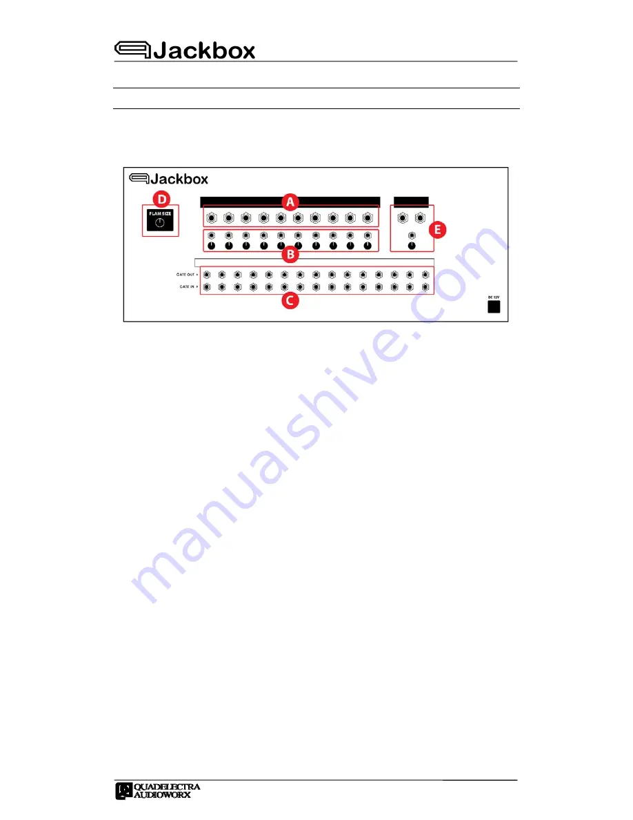
elements. Here's an abstract schematic, showing the main regions. 


Fig.3.a. The Jackbox back panel abstract design for both devices. 


A.


Individual Outputs: Jackbox Devices, expose a set of separate audio 

outputs, one for each fader of the front panel. Therefore the outputs 
are labelled after the front fader names, and will carry out their 
audio signal if -and only if- they are connected.  

 
If an audio output is left disconnected, the signal from its owning 
fader is passed through the main volume, and finally to the main 
output. 


B.


Level CV Inputs: Under each audio output, there is a CV Input jack, 
that allows you to control the volume of that output, from an 
external CV source. 
 
The Level CV Input will accept bipolar signals, that will be summed to 
the current volume of the owning fader. 
 

C.


Gate Ins & Outs: Jackbox units also expose a set of gate inputs and 
outputs, at the back. There is one pair (in & out) for each available 
drum sound.  


a.


Gate Ins, allow you to trigger single drum sounds using an 
external sequencer.  


b.


Gate Outs, allow you to connect trigger inputs from other 
devices, so that they can be controlled whenever a drum sound 
is played. 
 

Summary of Contents for Jackbox 7R-707

Page 1: ......

Page 2: ......

Page 3: ...er capabilities The TR 707 and 727 where essential producer choices in the days of early Chicago house music Legendary artists and bands have created some of their most classic tunes using these machi...

Page 4: ...e leftmost of the fader section the Accent Fader defines the amount of Accent to use when the Accent automation switch is enabled Note that Accent applies only when playing the drum pads The device wi...

Page 5: ...of the drum sounds on the device Most of the faders control one sound but there are also faders that control two For the faders that control grouped sounds the grouping is similar to the original har...

Page 6: ...UMPADS FADERS GROUPINGS BD1 BassDrum 1 LT Low Tom BD BassDrum BD1 BD2 BD2 BassDrum 2 MT Mid Tom SD SnareDrum SD1 SD2 SD1 SnareDrum 1 HT Hi Tom LT Low Tom LT SD2 SnareDrum 2 HC Hihat Closed MT Mid Tom...

Page 7: ...O HI HTIMB Hi TIMBale BG Bongo BONGO HI LOW BONGO LOW LTIMB Low TIMBale HC Hi Conga CONGA HI MUTE CONGA HI HI AGOGO LC Low Conga CONGA LOW CONGA LOW LOW AGOGO HTB Hi Timbale HTIMB CONGA MUTE CBSA CaBa...

Page 8: ...nected the signal from its owning fader is passed through the main volume and finally to the main output B Level CV Inputs Under each audio output there is a CV Input jack that allows you to control t...

Page 9: ...ice s main output which is stereo Note that although the individual outputs are mono the drum sounds are positioned in the stereo field when played through the main output Right below the stereo outpu...

Page 10: ...iginally present next to drum channel faders in the TR 7x7 series hardware is present in the rack extension too while the Flam Size switch which has no dedicated control in the original hardware is si...

Page 11: ...ss Drum 1 BD1 C3 36 3 Rim Shot RIM C 3 37 4 Snare 1 SD1 D3 38 5 Hand Claps HCLAP D 3 39 6 Snare 2 SD2 E3 40 7 Low Tom LTOM F3 G3 41 43 8 Closed Hi Hat HC F 3 G 3 42 44 9 Mid Tom MTOM A3 B3 45 47 10 Op...

Page 12: ...LBG C 5 61 3 Mute Conga MCG D5 62 4 High Conga HCG D 5 63 5 Low Conga LCG E5 64 6 High Timbale HTB F5 65 7 Low Timbale LTB F 5 66 8 Low Agogo LAG G5 67 9 High Agogo HAG G 5 68 10 Cabasa CS A5 69 11 Ma...

Page 13: ...e 67 Accent 68 Flam 128 BD Volume BG Volume 129 SD Volume HC Volume 130 LT Volume LC Volume 131 MT Volume HTB Volume 132 HT Volume LTB Volume 133 RIM COW Volume AG Volume 134 HCLP TAMB Volume CS MC Vo...

Page 14: ...727 Specifics 7 3 Back Panel 8 4 Features 10 4 1 Flam And Accent 10 4 2 Drum Sounds Outputs Stereo Image 10 APPENDIX I MIDI Note Assignments 11 AI 1 The 7R 707 MIDI Drum Mapping 11 Keyboard Lookup 11...

Reviews: