171.802UK User Manual
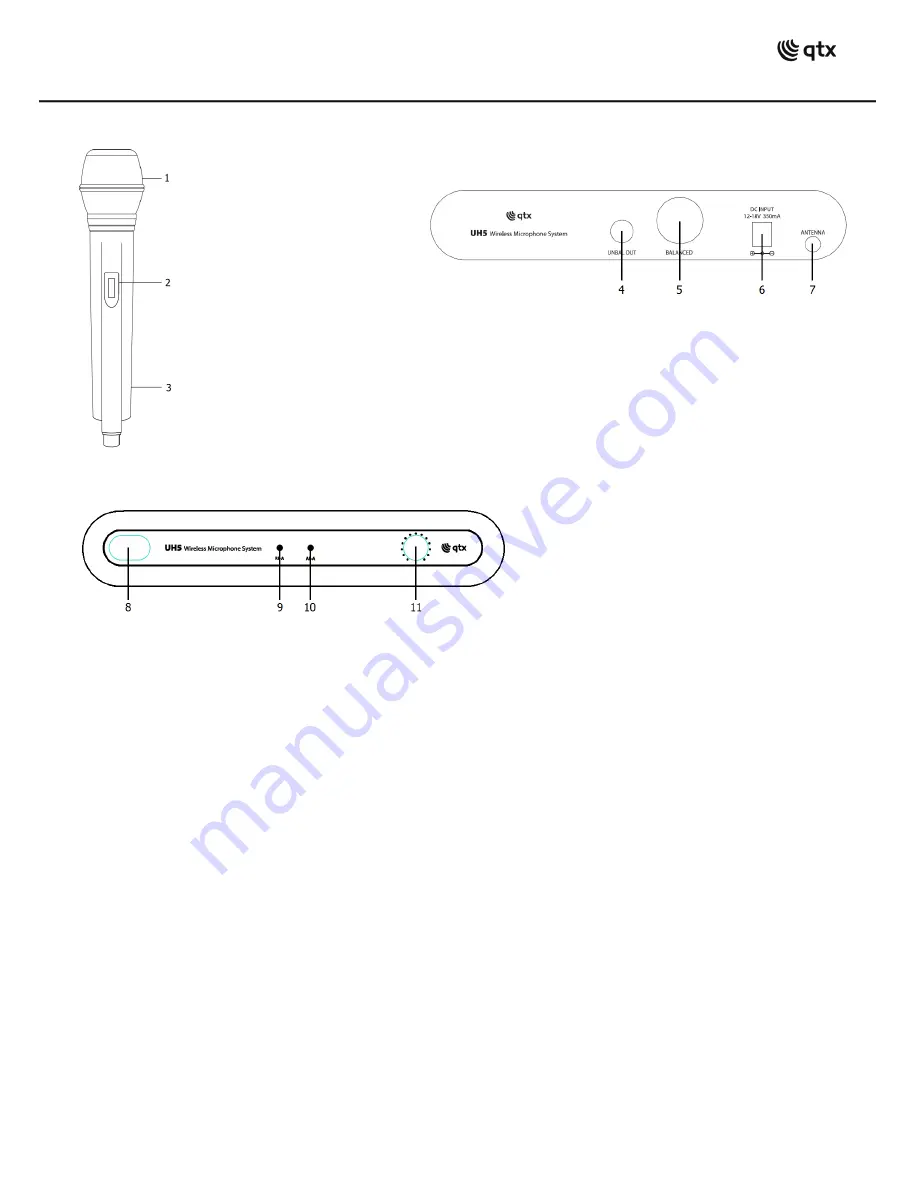
Handheld Transmitter
Receiver Rear Panel
Receiver Front Panel
Operation
Insert the supplied AA batteries by carefully sliding the rear battery compartment cover downwards to reveal the
compartment and install the batteries by sliding the first one to the top and inserting the second battery behind it, taking
care to observe the correct polarity.
Position the receiver within the best available line of sight to the transmitter and turn down the output level control.
Connect the DC jack of the supplied power adapter to the receiver and the plug-top to the mains outlet. Extend the
antenna upwards and outwards slightly and switch the power on.
Connect the jack or an XLR (optional) lead to the receiver’s audio output connector, turn down the volume of any
equipment (mixer, amplifier etc.) that the signal will be fed into and then connect the jack or XLR to the equipment.
Warning! - take care not to point microphones towards speakers – this can cause damaging feedback (loud whistle or
howling noise) – try to point microphones away from the speaker cabinets.
Move the switch on the handheld or bodypack transmitter to the first notch (MUTE) – the LED should light momentarily
(continuous dim LED indicates low battery). Move on another notch (ON) and gradually increase the microphone level(s)
on the receiver, then increase the volume on the mixer or amplifier until the sound from the microphone can be heard
through the equipment. Output level can then be adjusted to the required level from the receiver output level control and
the volume controls on the amplifier or mixer.
During use, it may be helpful for the reception of the microphone to be muted for a short period of time (e.g. to avoid
feedback when walking across the front of a speaker or avoid handling noise when placing the microphone down
momentarily or adjusting a neckband microphone). In these circumstances, it may be better to move the transmitter
switch to the “MUTE” position, which maintains the radio frequency carrier signal but mutes the microphone input.
When this switch is moved back to the “ON” position, the sound will be immediately restored without waiting for the
radio signal to be reinstated.
1.
Windshield
2.
Slide switch and LED
3.
Battery compartment
4.
Unbalanced jack output
5.
Balanced XLR output
6.
DC power inlet
7.
Antenna
8.
Power ON/OFF switch
9.
RF carrier indicator
10.
AF audio level indicator
11.
Output level control


